G
GGGGGGGGGGGGGGGGGGGGGGGGGGGGGGGG PRECAUTIONS Warning Unauthorized reproduction of all or part of this manual is strictly prohibited. The FIGURES in this manual are only for illustration purposes. They may differ from the actual product. The specifications and design of the product are subject to change without prior notice for purposes of quality improvement. Cautions To get the best use out of the product, be sure to read the cautions before using the product.
GGGGGGGGGGGGGGGGGGGGGGGGGGGGGGGG TABLE OF CONTENTS 1 INTRODUCTION .......................................................................5 Specifications .................................................................................................................................................. 5 Components .................................................................................................................................................... 5 Major Features ...............................
GGGGGGGGGGGGGGGGGGGGGGGGGGGGGGGG Zoom............................................................................................................................................................... 46 De-Interlace .................................................................................................................................................... 46 8 BACKUP ................................................................................ 47 Backup .............................................
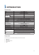
GGGGGGGGGGGGGGGGGGGGGGGGGGGGGGGG 1 INTRODUCTION Specifications VMAXD1 16 VMAXD1 8 Full D1 Digital Video Recorder 16Ch – D1 480/400 8Ch – D1 240/200 Linux Embedded - Built in Flash Memory 16 BNC 8 BNC System Format OS Video Input Video Output Monitor Spot Audio Input Audio Output Compression Format Recording Speed Recording Resolution Recording Mode Alarm Interface Video Output Resolution POS / ATM Interface Backup & Copy Access Network Access PTZ / Controller Access Internal HDD / Internal ODD System O
GGGGGGGGGGGGGGGGGGGGGGGGGGGGGGGG Major Features Advanced H.
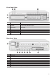
GGGGGGGGGGGGGGGGGGGGGGGGGGGGGGGG Front Panel View No 1 Name Power Button Description Turn ON or OFF. Authorization is required. 2 Lock Button Lock your system. Authorization is required. 3 Number Buttons Select channel. 4 5 6 Status Indication Optical Device Bay Functional Buttons Directional Button and Select Key Indicates each functional status. Door for CD-ROM Shortcut keys for the indicated function. 7 Use instead of mouse control.
GGGGGGGGGGGGGGGGGGGGGGGGGGGGGGGG 2 INSTALLATION & CONNECTION Connection Order By referring to the diagram above [Figure 2-1], make a connection accordingly. ཛ Connect CCTV Camera Signal to BNC Input on rear panel. ཛྷ Set video configuration with combination of dip switch. ཝ Connect display monitor to TV OUT on rear panel. No GUI is displayed through TV Out port. ཞ Connect VGA monitor to VGA OUT on rear panel and HDMI monitor to HDMI on rear panel.
GGGGGGGGGGGGGGGGGGGGGGGGGGGGGGGG Terminal Block The terminal blocks located in the rear of the VMAXD1 are for the connection of the PTZ, Sensor, Relay, and POS. The number of terminal blocks may vary depending on the model.G G PTZ Camera & Keyboard Controller Connect the PTZ control cable to the Terminal Block, TRXD+ and TRXD-, in the rear panel of the DVR. You may refer to “APPENDIX” in this manual for supported PTZ cameras. A keyboard controller has the same connection as a PTZ camera.
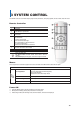
GGGGGGGGGGGGGGGGGGGGGGGGGGGGGGGG 3 SYSTEM CONTROL The VMAXD1 series can be controlled easily by using the front panel buttons, front panel jog/shuttle, remote controller, and/or the mouse.
GGGGGGGGGGGGGGGGGGGGGGGGGGGGGGGG 4 SETUP For Setup menu, click the right button of the mouse or press [Setup] button on the front panel. ID and Password are required for initial installation. Default ID and Password are shown below. Local Admin: 00000, User1 : 1111111, User2 : 2222222, User3 : 333333, User4 : 4444444 To change the password, right click on mouse, and click [Setup] > [System] > [Admin. Password].
GGGGGGGGGGGGGGGGGGGGGGGGGGGGGGGG Time Right-click the mouse button; then select [Setup] > [Time]. Time Sync Synchronize the time with the NTP (Network Time Protocol) server. The time will be synchronized with the NTP once every hour. If synchronization with the NTP server fails, synchronization with RTC will be established. £ Set the Time Sync to NTP or OFF. ¤ ¥ If NTP is selected, input the Server Type and Server URL. For automatic NTP setup, set Server Type to NTP and Server URL as Auto.
GGGGGGGGGGGGGGGGGGGGGGGGGGGGGGGG Time Zone £ ¤ Select your local Time Zone. Turn ON or OFF the daylight savings time (DST). ¥ If DST has been set to ON, select the Start Time and End Time for DST. For a weekly setting in the [Start Time] and [End Time] fields, set Day to 0. After the DST has been selected, the existing data will display as “OLD_” in the search and log list. Auto Reboot To help keep your system healthy, configure your VMAXD1 to reboot automatically.
GGGGGGGGGGGGGGGGGGGGGGGGGGGGGGGG Camera Right-click mouse button; then select [Setup] > [Camera]. Camera To setup a camera, select the Camera tab. Connect: Connect or disconnect the camera channel. ON means cameras is connected. To disconnect, turn camera OFF. When the camera channel is set to disconnected, the video contents will not be displayed even if the camera is actually connected. Name: Name each camera. £ Move mouse cursor above the name field and double click the left mouse button.
GGGGGGGGGGGGGGGGGGGGGGGGGGGGGGGG PTZ To setup a PTZ camera, select the PTZ tab. £ Select the Protocol for the PTZ camera you are using. ¤ ¥ Setup Camera ID and Baud Rate. Check your camera manual for the information. Set a Tour, so camera can automatically move between different presets. Configure up to two Tours, and each tour can have up to 8 presets ¦ If a tour has been set, set the Duration for the staying time when the tour is activated.
GGGGGGGGGGGGGGGGGGGGGGGGGGGGGGGG When the POS device has been configured, setup the VMAXD1 to record any transactions sent from the POS device. Go to [Setup] > [Recording] > [Recording], and make sure Text is set to ON.
GGGGGGGGGGGGGGGGGGGGGGGGGGGGGGGG User can perform a search by looking up an item on the POS transaction. ཛ To perform a search based on POS transactions, click the right mouse button during Playback Mode, and click [Text Search] > [CH##]. ཛྷ A Keyboard will appear. Using the mouse, type in the item you wish to search; then click Search button. The keyboard is case sensitive. ཝ ཞ The first recorded image with the item will appear. Use the Playback Control Bar to playback the video.
GGGGGGGGGGGGGGGGGGGGGGGGGGGGGGGG Motion Select the Motion tab to configure the motion detection settings. £ Select Motion Area of each channel. ¤ ¥ When clicked, the single channel mode composed of square boxes appears on the screen. Use the mouse to select areas you wish to disable motion detection. Areas where motion detection is disabled will be indicated in the color brown. Select Motion Area of each channel. ¦ When clicked, the single channel mode composed of square boxes appears on the screen.
GGGGGGGGGGGGGGGGGGGGGGGGGGGGGGGG Relay Select from NO (Normally Open) or NC (Normally Closed). If the wrong type is selected, relay will not work. NO, which is normally open, closes when a signal is received. NC, which is normally closed, opens when a signal is received. Relay Output Connection Relay output signal to external device such as Alarm or Siren. Connect relay to R1, R2, R3, and/or R4 of the terminal block, located on the rear side with R#_Com Port.
GGGGGGGGGGGGGGGGGGGGGGGGGGGGGGGG Recording The Recoding setup is to configure the environment of the system’s record configuration and major functions. VMAXD1 allows you to create a more detailed recording schedule by setting four unique record configurations. Right-click mouse button; then select [Setup] > [Recording]. Select the specific schedule (Schedule1, Schedule2, Schedule3, Schedule4) you wish to configure, and change the settings for the selected recording schedule.
GGGGGGGGGGGGGGGGGGGGGGGGGGGGGGGG Recording Set the details for the recording image and the recording speed. G G Recording Resolution: Set the resolution of the recorded channels. Select from CIF, 2CIF, and 4CIF. Recording Resolution CIF 2CIF 4CIF NTSC 352*240 704*240 PAL 352*288 704*288 704*576 704*480 Recording Quality: Set the quality of the recorded channels. Select from Lowest, Low, Middle, High, and Highest. ଖ The higher the quality, the larger the file size will be.
GGGGGGGGGGGGGGGGGGGGGGGGGGGGGGGG Alarm This feature is used to generate alarms through the PTZ Preset, E-mail, Spot 1, Popup, and/or Callback in case of an event. You can configure up to eight presets (1-8). ଖ Popup function is to inform event occurrence to the user through a warning window in the real-time monitoring mode. Buzzer: Makes a beep sound when event is triggered. PTZ Preset: Set preset number. When event is triggered, PTZ camera will move to the selected preset.
GGGGGGGGGGGGGGGGGGGGGGGGGGGGGGGG Duration Pre Alarm: Set as ON or OFF. If ON is selected, the VMAXD1 will record the frames of the last 7 seconds before the event occurrence. Post Alarm: Set the duration you wish the VMAXD1 to record immediately after the event has ended. Select from 5, 10, 15, 20, 50, 100, and 300 seconds. Log Set the VMAXD1 to generate and save specific log categories—Motion, Sensor, Sound, Pattern, and Text. If set as ON, the VMAXD1 will save the logs of that category.
GGGGGGGGGGGGGGGGGGGGGGGGGGGGGGGG Advanced Watermark: Set as ON or OFF. QP Control: This will help adjust the size of the files that need to be saved by adjusting the quality of the image. Select from CBR or VBR. CBR will give you consistent file sizes but different image qualities. VBR will give you consistent image qualities but different file sizes. CBR and VBR can be set in 5 different levels, depending on the recording quality.
GGGGGGGGGGGGGGGGGGGGGGGGGGGGGGGG Schedule VMAXD1 allows you to create a more detailed recording schedule by combining four unique record configurations on a weekly 24 hour basis. Right-click mouse button; then select [Setup] > [Schedule]. Select the specific schedule configuration (Schedule1, Schedule2, Schedule3, Schedule4) you wish to apply to the schedule, and use your mouse to select the time block(s) you wish to apply the configuration to. Hour Button: Select all days and time.
GGGGGGGGGGGGGGGGGGGGGGGGGGGGGGGG Disk Configuration In the Storage menu, remember to save the new settings after making changes. If not, the new settings will not be applied to the system. The system will initializes the menu to the basic setting. Auto Deletion Set a limit on the number of days within a month your VMAXD1 can record. Select from None, 1Day, 7Days, 30Days, or User Setting (1-31). HDD Overwrite £ Turn ON or OFF.
GGGGGGGGGGGGGGGGGGGGGGGGGGGGGGGG When removing a HDD installed to the VMAXD1 or a storage device connected to the VMAXD1 through a USB port, the user must execute the [Eject] command first. Backup: The storage devices placed in Backup will only be used for backing up data. They can never be used to store data. Depending on the storage type, the storage can only be used for Recording or Backup purposes.
GGGGGGGGGGGGGGGGGGGGGGGGGGGGGGGG Network Configuration Ethernet Select TCP/IP or ADSL and input the necessary information to connect your VMAXD1 to the network. TCP/IP: Uses a fixed IP in the Local Area Network environment. £ Go to [Setup] > [Network Config] > [Network]. ¤ Check the box to use TCP/IP. ¥ Enter the IP Address, Subnet Mask, Defualt Gateway, Primary DNS, and Secondary DNS. ¦ Click [Save]. ADSL: Uses the user authentication-type ADSL communication environment. £ Check the box to use ADSL.
GGGGGGGGGGGGGGGGGGGGGGGGGGGGGGGG DDNS As part of the DNS system, the Dynamic Domain Name Server (DDNS) updates IP addresses of the host name in real-time and assigns fixed domain names to the systems linked to that DNS server, allowing users to use the same DNS name regardless of the change in the IP address. DDNS provides dynamic IP addresses to ensure URL access. User can monitor the VMAXD1 from a remote location, using the built-in web server.
GGGGGGGGGGGGGGGGGGGGGGGGGGGGGGGG Client Configuration Go to [Setup] > [Network Config] > [Client Configuration]. The Ports need to be set in order for the VMAXD1 to connect to the client software(s) properly. CMS (VMS) Port: This is used to connect the VMAXD1 to a CMS or VMS software. The default value is between 2000 and 2007. A randomly chosen value can be used depending on the network environment. Web Server Port :This is used to connect the VMAXD1 to a remote software. The default value is 80.
GGGGGGGGGGGGGGGGGGGGGGGGGGGGGGGG Max Transfer Speed This configures the settings for the data sent over the network. Go to [Setup] > [Network] > [Max Transfer Speed]. Select the settings of the picture(s) that you wish to send over the network. Picture Resolution: Adjust the resolution of the picture(s) that are sent over the network. Picture Quality: Adjust the quality of the picture(s) that are sent over the network.
GGGGGGGGGGGGGGGGGGGGGGGGGGGGGGGG Callback This feature will transmit a signal to a callback server located at a remote site and begin recording automatically. £ Check the Callback box to turn ON this function. ¤ ¥ Configure the Callback Server IP, Port Number, User ID, and Event Type. For the Callback Server IP, user can enter an IP or a URL. ¦ The port number should be over 2000 and should not overlap with the set values at [Setup] > [Network] > [Client Configuration].
GGGGGGGGGGGGGGGGGGGGGGGGGGGGGGGG System DVR Name The default name is the MAX Address of the VMAXD1, but the name can be changed. The new name can consist of up to 20 letters. ID for Remote Controller To use remote controller, this ID must match the Remote Controller ID. If not, the remote controller will not be able to send input singles to the VMAXD1. The numbers 1 ~ 255 can be used as the ID.
GGGGGGGGGGGGGGGGGGGGGGGGGGGGGGGG Upgrade Easily upgrade your VMAXD1 firmware or the VMAXD1 firmware or the Setup Menu Settings using an external or portable storage device. Make sure the storage device that contains the upgraded file is connected to the VMAXD1. Click Firmware to upgrade the VMAXD1 firmware. Click Setup to upgrade the setting values of the Setup Menu. ଖ Find and copy the upgrade file to the highest folder in the external storage device or portable storage device that supports USB 2.0.
GGGGGGGGGGGGGGGGGGGGGGGGGGGGGGGG Error Alarm Action Select how you wish to be notified of any alarm errors (Video Loss Signal, HDD Full, Fan Failed, HDD Failure, and Storage Warning). £ Go to [Setup] > [System]. ¤ On the Error Alarm Action selection widow, select how to be notified of the alarm. Select from Off Buzzer, E-mail, Relay01, and Popup Window. ଖ Warning Window (Popup) If Popup is selected, this Warning window will appear on the real-time monitoring screen.
GGGGGGGGGGGGGGGGGGGGGGGGGGGGGGGG 5 LIVE Real Time Live View After booting is finished, Audio, Recording Status, Channel Title, Connection Status, Time, and HDD Status are all displayed.
GGGGGGGGGGGGGGGGGGGGGGGGGGGGGGGG Status Icons Recording Event Motion Detection Recording Sensor Recording Audio Recording Pattern Change Recording Text Recording G Recording Event Icons are still displayed even when recording has been stopped. G Recording Mode Video Recording Audio Recording Text Recording G Recording Mode Icons distinguish recording status. Monitoring Mode Video is not connected or Video is covert. Audio is set activated. Audio is set as silent. No Signal Camera has been disconnected.
GGGGGGGGGGGGGGGGGGGGGGGGGGGGGGGG System Login System users are divided into local administrators and general users. The local administrator can use all functions of the VMAXD1. Local Admin The local administrator can use all functions: System Power On/Off, Setup, Live View, and Playback. However, remote access is not available. User Up to four users are allowed. Each user can access the functions depending on the given authorities. For Authorization Setup, go to [Setup] > [System] > [Users].
GGGGGGGGGGGGGGGGGGGGGGGGGGGGGGGG Screen Division and Auto Sequence After the system has booted, images will be displayed on a 9 or 16 Screen Division Mode, depending on the model. The system follows user’s setting for the screen division, once the DVR has been rebooted. VMAXD1 Series provides the following screen division modes: 1, 4, 9, Big, 16, Biggest, and Auto Sequence. 1, 4, 9, and 16 are Basic Screen Division Modes. Big, Biggest, and Auto Sequence are Special Screen Division Modes.
GGGGGGGGGGGGGGGGGGGGGGGGGGGGGGGG Zoom This feature enables users to zoom in and/or out a single channel mode display during Real-Time Monitoring Mode. ཛ Click the right mouse button, and click the Magnifying Glass icon located on right corner of the Menu. ཛྷ After selecting a channel, the Single (1) Channel Display will appear with the zoom control screen displaying at the bottom-right. ཝ ཞ ཟ ¨ Move the mouse pointer to an area in the zoom control screen that you wish to magnify and double-click it.
GGGGGGGGGGGGGGGGGGGGGGGGGGGGGGGG 6 SEARCH Express Search Express search is the calendar search. This allows you to search and playback by Date & Time, Multi-Channel, MultTime, Multi-Day, and/ Event. In the real-time monitoring mode, click the right mouse button, and select [Search] > [Express Search]. Date and Time Search ཛ Select the desired date. The red triangle located at the top-left of the dates in the calendar indicates that recorded data exists. ཛྷ Select the Hour (0 ~ 23).
GGGGGGGGGGGGGGGGGGGGGGGGGGGGGGGG Searching by the file list is only available in the Multi-Channel Search Current Old Number Recorded image files with the current set time Recorded image files before the time change Event Event is used to search for a recorded data by events. Select All, Motion, Sensor, Audio, and/or Text. Multi-Channel Search The Multi-Channel Search is to play recorded images of the different channel over a certain period of time.
GGGGGGGGGGGGGGGGGGGGGGGGGGGGGGGG 7 PLAYBACK VMAXD1 Series provide a variety of playback functions: Smart Search, PCD Search, Express Search, Text Search, Multi-Time, Multi-Day, Multi-Channel, Panorama Playback, Event Playback, and Audio Playback. To go to Playback mode, click the button located on the Control Bar of real-time monitoring mode. Playback Control Bar ཛ ཛྷ In the Playback mode, user can playback video contents by using the buttons shown below.
GGGGGGGGGGGGGGGGGGGGGGGGGGGGGGGG 6 Forward Frame by Frame 7 Forward Play / Fast Forward Forward Playback Frame-by--Frame Pause For every click the speed will increase. The speed ranges from x1 to x30. Selecting the right-mouse button or menu button in the Playback Mode opens the Playback Menu as shown below. Smart Search This feature is used to search an image for movement within a specific zone. ཛ ཛྷ Go to Smart Search and select the desired channel. The screen will shift to the 32X24 grid mode.
GGGGGGGGGGGGGGGGGGGGGGGGGGGGGGGG Express Search Click the right mouse button during Playback mode, and select [Express Search]. The Search window will appear. Multi Time The user can playback the video contents of the certain channel recorded in different time zones simultaneously. The search results are ordered from the oldest to the most recent videos. Click the right mouse button during Playback mode, and select [Multi Time]. View “Search” for more details.
GGGGGGGGGGGGGGGGGGGGGGGGGGGGGGGG Backup Capture and backup an image onto a CD or an External Device. Backup: Save the image onto a CD or External Device. Snapshot: Capture and save the displayed screen. Zoom Move to Zoom Mode. See “Live” for more details. De-Interlace Ally de-interlace to the image.
GGGGGGGGGGGGGGGGGGGGGGGGGGGGGGGG 8 BACKUP To backup the data, the PC shall be equipped with CD and DVD or connected with a storage device such as HDD, CD and DVD via the USB 2.0 port. For supported external devices, refer to “APPENDIX”. The user can backup data in the real-time monitoring, search, log, or playback mode. VMAXD1 also features NAS (Network Attached Storage) Backup. User can backup data in real time monitoring, search, log, or playback mode.
GGGGGGGGGGGGGGGGGGGGGGGGGGGGGGGG Backup ཛ Right click mouse button during real-time monitoring mode; then click [Backup] > [Backup]. ཛྷ A list of the devices that can be selected is outputted with simple information of the currently selected devices ཝ When a device is selected, the free space and total capacity for the selected device are displayed. ཞ To change the start and end time, press the Select button and adjust the date and time using the arrow keys.
GGGGGGGGGGGGGGGGGGGGGGGGGGGGGGGG Capture The Capture function allows the user create a JPG file in monitoring, playback, search, or log mode, and then, save the image data. ཛ To backup the currently displayed image, right click mouse button during real-time monitoring mode; then go to [Backup] > [Capture]. ཛྷ When only one USB2.0 backup device (excluding ODD devices) is searched, the JPG file is stored in the same device. ཝ If there are no or more than two USB2.
GGGGGGGGGGGGGGGGGGGGGGGGGGGGGGGG Setup Backup The Setup Backup is to save the current menu settings. This function enables the user to copy the settings and apply the same settings to other systems. ཛ For the Setup Backup, a device for backup must be connected. ཛྷ Right click mouse button during real-time monitoring mode; then go to [Backup] > [Setup Backup] and a window shown below appears. The setup is copied by the name shown below. Saved as the name below.
GGGGGGGGGGGGGGGGGGGGGGGGGGGGGGGG 9 PTZ Setting a PTZ Camera This allows users to monitor live view, using a PTZ camera. Connect the PTZ camera to the VMAXD1. For details on external connection, refer to “Terminal Block” in this manual. £ Select [Setup] > [Camera] > [PTZ]. ཛྷ Configure the Protocol, ID, Baud Rate, Duration, and/or Tour. Baud Rate can be selected at 2400, 4800, 9600, 19200, or 38400. Duration can be selected at 5, 10, 15, 20, 5-60 (User Setting) seconds.
GGGGGGGGGGGGGGGGGGGGGGGGGGGGGGGG Controlling a PTZ Camera ཛ ཛྷ To control a PTZ camera, go to [Menu] > [PTZ] or press PTZ button on the remote controller. Select Channel of the PTZ camera you wish to control. Direction Keys: Adjust the PTZ camera to look at a different scene. Wide: Zoom Out Tele: Zoom In Min. / Max.: Change PTZ controller to Min or Max mode. Speed: 1 ~ 100; Adjust the speed of the PTZ camera.
GGGGGGGGGGGGGGGGGGGGGGGGGGGGGGGG 10 System Information Version Displays all the general system information. Go to [Menu] > [ Information] > [Version].
GGGGGGGGGGGGGGGGGGGGGGGGGGGGGGGG System Log Displays recorded event log information for each day. Go to [Menu] > [ Information] > [System Log]. ཛ ཛྷ ཝ ཞ ཟ Go to [Setup] > [Information] > [System Log]; then the System Log window will appear. Using the mouse or the arrow keys and SELECT button, select a desired date on the activated Calendar. The user can check the time and the log type by using the arrow keys in the log list. Use the Up/Down button to check the logs by time and type on each page.
GGGGGGGGGGGGGGGGGGGGGGGGGGGGGGGG Miscellaneous Control Turn ON or OFF the external devices. Go to [Menu] > [ Information] > [Misc Control]. Audio Select the Audio tab; then, select the channel(s) to be activated or Mute. VMAXD1 16 supports 16 channels of audio, and VMAXD1 8 supports 8 channels of audio. Relay Select the Relay tab; then, select those you wish to activate. VMAXD1 16 supports 4 channel inputs, and VMAXD1 8 supports 2 channel inputs.
GGGGGGGGGGGGGGGGGGGGGGGGGGGGGGGG Monitor Configuration Configure the Camera Title, Control Bar, Button Sound, HD Frequency, Screen Saver, Spot Sequence, Main Sequence, and TV Adjustment. Select [Information ] > [Monitor Configuration], and the Single Channel Screen Mode will display with Monitor window. Camera Title: Turn ON to display the camera title on the display screen. Control Bar: Turn ON to display the control bar on the live view.
GGGGGGGGGGGGGGGGGGGGGGGGGGGGGGGG 11 REMOTE ACCESS There are two types of remote software available: PC Web Viewer and Mobile Web Viewer. Features Live Monitoring and Playback Relay Control and Two-Way Audio Screen Capture Digital Zoom PTZ Control Preset Movement Remote Detail Setup Connection ཛ ཛྷ ཝ ཞ Open Internet Explorer and enter the IP Address for your VMAXD1. Select PC or Mobile Web Viewer. Enter the Port (2000), Username, and Password.
GGGGGGGGGGGGGGGGGGGGGGGGGGGGGGGG Live Mode Display real-time live view of connected camera by clicking display. Image button. If no cameras are connected, an image will not Name Description Display Mode Used to change the screen division mode. Sequence Activate sequence of connected cameras. PTZ Control Use to control PTZ camera. This can be used on live mode. Capture Use to capture the current display image. When clicked, the capture image will appear.
GGGGGGGGGGGGGGGGGGGGGGGGGGGGGGGG Playback Mode Display playback mode by clicking No 1 Name Live / Playback button. Playback Mode also allows user to search recorded data. Description Switch display from Live Mode to Playback Mode or Vice Versa. Use to capture the current display image. When clicked, the capture image will appear. Click the right mouse button and press Save As to save the captured image. Click the right mouse button and press Print to print the captured image.
GGGGGGGGGGGGGGGGGGGGGGGGGGGGGGGG Application Setup Enables user to set the filter option for display image and the duration time for the Sequence function. Adjust Allows user to adjust the image color, brightness, and other camera settings. DVR Setup Manager Contains all configuration setup information like your VMAXD1 system. User can remotely configure most of the settings with this tool. Search Perform a Date & Time Search with this feature. ཛ Select Search button.
GGGGGGGGGGGGGGGGGGGGGGGGGGGGGGGG 12 DNA DNA stands for DVR Network Agent. It connects to the DVR(s) and controls it from a remote location. Setup Install DNA Remote Client Software on your PC for powerful remote client features. We recommend all users to download DirectX 9.0 before installation. To install DirectX 9.0, go to [http://www.microsoft.com]. ཛ ཛྷ ཝ Insert the included CD in your client PC. Select [DNS.msi] file. The following window will appear. Press [Next]. ཞ Select User and press [Next].
GGGGGGGGGGGGGGGGGGGGGGGGGGGGGGGG ཟ Installation will begin. Press [Close] when it is completed.
GGGGGGGGGGGGGGGGGGGGGGGGGGGGGGGG User Interface No 1 Name Information Button Displays DNA version number. Description 2 Display Mode Switch to Full Screen or Minimize the window. 3 Exit Power OFF the DNA Software. 4 Site List 5 Settings / Save and Print 6 Mode DVR and Cameras listed on DVR/CH. DVR(s) registered as a favorite will be listed on the Favorite list. Configuration: Enter Setup menu. Print: Print current page. Snapshot: Capture and save current video image.
GGGGGGGGGGGGGGGGGGGGGGGGGGGGGGGG Configuration Adding a DVR ཛ Login to the DNA software. User ID is Admin. Password is 00000000. ཛྷ ཝ ཞ ཟ Enter [Configuration]. Under DVR Group/DVR/Camera list, select [DVR] and click the right mouse button. Select [Add Group] and type a name for the new group. Select the new group and click the right mouse button. Then, select [Add DVR]. Adding a User ཛ ཛྷ ཝ ཞ ཟ Enter [Configuration]. Select [User] from the left column.
GGGGGGGGGGGGGGGGGGGGGGGGGGGGGGGG Assigning User(s) to a DVR ཛ ཛྷ ཝ ཞ ཟ Enter [Configuration]. Select [User-DVR-Assignment] from the left column. To grant access to the DVR, drag and drop the registered DVR in the middle column to the User(s) you wish to give access to. Select [Add User]. Enter the user information to the right.
GGGGGGGGGGGGGGGGGGGGGGGGGGGGGGGG Playback DNA enables you to search and playback recorded videos remotely. ཛ ཛྷ ཝ ཞ ཟ Select . The calendar will appear. Select the date which has the recorded video. Press [OK] button. The results will display in [Open File] window. Select the data you wish to see, and click [OK]. Time Date Search View the results as a timeline by clicking [Time/Date Search] tab on the top of the window. User can easily select a different date and time.
GGGGGGGGGGGGGGGGGGGGGGGGGGGGGGGG Remote File Recorded videos for the searched date will appear. Each line represents one hour time increments.
GGGGGGGGGGGGGGGGGGGGGGGGGGGGGGGG Control Of Select the alarm output, and logs. tab for information on the DVR, such as connected cameras, motion detection, sensor input, The logs are separated into the categories All, Fail, Network, Record, and Normal. Through Control, you can enter the setup configuration on your connected device. Setup pages will differ according to the device.
GGGGGGGGGGGGGGGGGGGGGGGGGGGGGGGG Event Event page displays current incoming event(s). User can play the event as a playback. ཛ Select a specific event. ཛྷ Right click mouse button and click [Play].
GGGGGGGGGGGGGGGGGGGGGGGGGGGGGGGG 13 RAID The VMAXD1 supports RAID 1 and RAID 5 (Up to 8 Terabytes). Configuring RAID £ Prepare the hard drives and connect to the VMAXD1. RAID 1 requires more than 2 HDDs. RAID 5 requires more than 5 HDDs. ¤ Turn VMAXD1 ON. Right click VMAXD1 and go to [Setup] > [Disk Config] > [New]. ¥ Select the HDD and click [RAID 1 Creation]. For RAID 5, select [Raid 5 Creation]. ¦ § ¨ Press OK to initialize RAID. When completed, RAID will move to Recording tab.
GGGGGGGGGGGGGGGGGGGGGGGGGGGGGGGG Destroying RAID Destroy RAID to return to normal recording from RAID configuration. £ Right click VMAXD1 and go to [Setup] > [Disk Config] > [Recording]. ¤ Select the RAID you wish to destroy; then click RAID Destroy. If RAID Destroy is not selectable, select Offline first. ¥ Click YES when the popup window appears. .
GGGGGGGGGGGGGGGGGGGGGGGGGGGGGGGG APPENDIX Recommended HDD Specification Type Size Capacity Buffer RPM SATA I, II 3.5“ 1, 2 Flat Up to 1.5TB over 8MB over 7200 Recommended PTZ Camera Protocol Vendor Model Digital Watchdog Digital Watchdog CHOU ULTRA_7 ULTRA_8 COHU3925 Dongyang Dongyang DYNACOLOR DSCP A.D.
G
GGGGGGGGGGGGGGGGGGGGGGGGGGGGGGGG 5436 W Crenshaw Street Tampa, FL 33634 Toll Free: 866-446-3595 Tel: 813-888-9555 Fax: 813-888-9262 www.Digital-Watchdog.com technicalsupport@dwcc.