
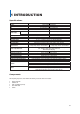
Specifications


GGGGGGGGGGGGGGGGGGGGGGGGGGGGGGGG
8
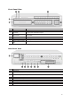
Connection Order
By referring to the diagram above [Figure 2-1], make a connection accordingly.
ཛ Connect CCTV Camera Signal to BNC Input on rear panel.
ཛྷ Set video configuration with combination of dip switch.
ཝ Connect display monitor to TV OUT on rear panel.
No GUI is displayed through TV Out port.
ཞ Connect VGA monitor to VGA OUT on rear panel and HDMI monitor to HDMI on rear panel.
On VGA and HDMI Output, only the channel title is shown.
For higher resolution (greater than HD), only VGA Output is available.
ཟ Connect Spot Monitor to SPOT # on rear panel.
འ The following devices can also be connected:
Devices
DVR Terminal
Internal Hard Drives
6 SATA
Spot Monitor
4 BNC for 16 Channel
1BNC for 8 Channel
Audio
Each Channel
Sensor
Each Channel
Relay
4 for 16 Channel
2 for 8 Channel
POS
8 Connections for 16 Channel
4 Connections for 8 Channel
2 INSTALLATION & CONNECTION