DEClaser 1100 Printer Installation Guide Order Number EK–DCL11–IN–002 Digital Equipment Corporation Maynard, Massachusetts
First Printing, January 1991 Revised, June 1991 The information in this document is subject to change without notice and should not be construed as a commitment by Digital Equipment Corporation. Digital Equipment Corporation assumes no responsibility for any errors that may appear in this document. Any software described in this document is furnished under a license and may be used or copied only in accordance with the terms of such license.
First Printing, January 1991 Revised, June 1991 The information in this document is subject to change without notice and should not be construed as a commitment by Digital Equipment Corporation. Digital Equipment Corporation assumes no responsibility for any errors that may appear in this document. Any software described in this document is furnished under a license and may be used or copied only in accordance with the terms of such license.
FCC NOTICE: This equipment generates and uses radio frequency energy and if not installed and used properly, that is, in strict accordance with the manufacturer’s instructions, may cause interference to radio and television reception. It has been type tested and found to comply with the limits for a Class B computing device in accordance with the specifications in Subpart J of Part 15 of FCC Rules, which are designed to provide reasonable protection against such interference in a residential installation.
Contents v Preface Chapter 1 Preparing Your Site 1.1 1.2 1.3 Power Requirements . . . . . . . . . . . . . . . . . . . . . . . . . . . . . . . Operating Location Requirements . . . . . . . . . . . . . . . . . . . . . Environmental Conditions . . . . . . . . . . . . . . . . . . . . . . . . . . . 1–1 1–2 1–3 Chapter 2 Unpacking Your Printer 2.1 2.2 2.3 Printer Inventory . . . . . . . . . . . . . . . . . . . . . . . . . . . . . . . . . . DEClaser 1100 Printer Components . . . . . . . . . . . . . . . . . .
Appendix A Cabling Information A.1 Cable Combinations . . . . . . . . . . . . . A.2 Interface Programming Instructions A.2.1 Serial Flow Control . . . . . . . . . . . A.2.2 Parallel Communication . . . . . . . . . . . . . . . . . . . . . . . . . . . . . . . . . . . . . . . . . . . . . . . . . . . . . . . . . . . . . . . . . . . . . . . . . . . . . . . . . . . . A–1 A–5 A–5 A–6 Cables and Adapters for Communication Connections . . . . . .
Preface The DEClaser 1100 printer is a nonimpact, desktop, page printer. This guide covers the installation of the DEClaser 1100 printer up to the point where it is operating properly. All operating information can be found in the DEClaser 1100 Printer Operator’s Guide. Intended Audience This guide is written for installers of the DEClaser 1100 printer. The installation procedure is designed to be followed in order beginning with Chapter 1.
Ordering Additional Copies of This Documentation Set The documentation set consists of one of each of the following: • DEClaser 1100 Printer Installation Guide • DEClaser 1100 Printer Operator’s Guide • Spine insert for the binder • Three-ring binder You can order additional copies of this documentation set from DECdirect as described in the ordering information section in the DEClaser 1100 Printer Operator’s Guide. The ordering number for the documentation set is EK– D1100–DK.
Conventions The following conventions are used in this guide: Convention Meaning NOTE Notes provide important additional information. CAUTION Cautions provide information to prevent equipment damage. WARNING Warnings provide information to prevent personal injury. Key A key name is shown enclosed in a box to indicate that key on the control panel. Key names are always shown in initial capital letters. For example: 1. Dash (—) Press to place the printer on line.
Human Services (DHHS) Radiation Performance Standard according to the Radiation Control for Health and Safety Act of 1968. The printer does not emit hazardous light since the laser beam is totally enclosed during all modes of customer operation and maintenance. WARNING: Use of controls or adjustment procedures other than those specified in this manual may result in hazardous laser light exposure. CDRH Regulations The Center for Devices and Radiological Health (CDRH) of the U.S.
Chapter 1 Preparing Your Site Electrical and environmental conditions surrounding the work location can affect the performance of the DEClaser 1100 printer. This chapter lists the requirements for installing the DEClaser printer in a location where it performs best. 1.
1.2 Operating Location Requirements Install the DEClaser 1100 printer in an area that meets the following requirements: • A flat, level surface free from vibrations • Enough space to allow ventilation and easy access to all sides of the printer for servicing The following figure illustrates the space requirements for the printer when the optional printer feeder unit is not installed.
The following figure illustrates the space requirements for the printer when the optional printer feeder unit is installed. mlo-005807 1.3 Environmental Conditions Your operating site should abide by the following environmental requirements. • To ensure proper operation, maintain the printer site within a temperature range of 10°C to 32.5°C (50°F to 91°F). • To ensure consistent image quality and to prevent paper jams, maintain a humidity range of 20% to 80% (noncondensing).
Chapter 2 Unpacking Your Printer This chapter explains how to unpack the DEClaser 1100 printer and identifies printer components. CAUTION: Do not power on the printer until instructed to do so. 2.1 Printer Inventory Your DEClaser 1100 printer and accessories come packaged in two separate boxes. NOTE: For 240-volt printers, the serial interface cable and the power cord are packaged in a separate box called a country kit.
The following illustrations show the correct and incorrect methods of lifting the printer. CAUTION: When moving the printer from one location to another, close the paper tray and hold the printer firmly at the bottom with both hands.
Never lift the printer by the paper output tray slot.
2.2 DEClaser 1100 Printer Components The following illustration shows the front view of the printer with the major components identified.
Number Description 1 Control panel 2 Top output tray 3 Paper stop 4 Font cartridge slots 5 Power switch 6 Front cover release button 7 Paper tray 8 Extension tray 9 Adjustable paper guide 10 Fixing assembly cover 11 Front cover Unpacking Your Printer 2–5
The following illustration shows the rear view of the printer with the major components identified.
2.3 Removing the Shipping Material Remove all shipping and packing material using the following procedure. 1. Remove the printer from the plastic bag. 2. Remove the shipping tape from the front of the printer. Discard the plastic bag and the shipping tape.
3. Open the paper tray by pulling it toward you.
4. Lift up the release button to open the front cover.
5. Remove the orange-colored packing stopper by squeezing and then lifting it out. Discard the packing stopper. mlo-006612B 6. Continue with Chapter 3 to install the EP-L cartridge.
Chapter 3 Installing the EP-L Cartridge This chapter describes how to install the EP-L cartridge. When handling the EP-L cartridge, be sure you: • Install the EP-L cartridge immediately after removing it from its protective bag. • Keep the cartridge away from CRTs, disk drives, and floppy disks. The magnet in the cartridge can damage the data they contain. • Use the cartridge before its expiration date; otherwise, print quality may deteriorate. • Do not stand the cartridge on end or upside down.
1. Remove the EP-L cartridge from its shipping carton.
2. Remove the EP-L cartridge from its protective bag.
3. Hold the cartridge as shown and gently rock it five or six times to distribute the toner evenly. NOTE: Do not shake the cartridge vigorously.
4. Remove the sealing tape from the cartridge by holding the cartridge on a flat, stable surface and gently pulling the orange tab straight out of the cartridge. CAUTION: Pull the tab straight out of the cartridge. Pulling the tab at an angle can snap or cut the sealing tape. – The sealing tape is about 457 mm (18 in.) long and may have toner on it. If you get toner on your hands or clothing, wash with cold water and soap. Discard the sealing tape.
5. Insert the EP-L cartridge by aligning the arrow on the cartridge with the mark on the printer, and gently push the cartridge in until it stops.
6. Slowly close the front cover. NOTE: If the EP-L cartridge is not pushed in completely, the front cover will not close.
Chapter 4 Connecting the Printer Your printer is equipped with the following interface connectors: • Serial • Parallel • Video This chapter explains how to connect the serial and the parallel interface connectors. Refer to Appendix A for detailed information on connecting your DEClaser printer to various host devices. Appendix A lists adapters for both the host and the printer and lists hosts that do not accept the BC16E serial interface cable.
4.1 Serial Interface Connection The serial interface connection uses the supplied BC16E serial interface cable and the H8571–E serial interface adapter. CAUTION: Before connecting the parallel interface cable, be sure the host device you are connecting to is turned off. Follow these directions for the serial interface connection: 1. Attach the H8571–E serial interface adapter to the serial interface connector on the back of the printer.
2. Plug one end of the BC16E serial interface cable into the H8571–E serial interface adapter. mlo-005819 3. Plug the other end of the BC16E serial interface cable into the serial interface connector on the host device.
4.2 Parallel Interface Connection This procedure uses an optional BC19M–10 parallel interface cable to describe the parallel connection to the printer. You must order the BC19M– 10 parallel interface cable through DECdirect or through your Digital sales representative. CAUTION: Before connecting the parallel interface cable, be sure the host device you are connecting to is turned off. 1. Plug the other end of the BC19M–10 cable into the parallel interface connector on the printer.
4.3 Power Source Connection Use the following procedure to connect the printer to the wall outlet. 1. Make sure the printer power switch is in the OFF (O) position.
2. Plug the power cord into the power cord receptacle. mlo-005720 3. Insert the other end of the power cord into the wall outlet. WARNING: Do not use a grounding adapter plug on the power cord. You must have a grounded wall outlet that accepts a 3-pronged plug.
Chapter 5 Loading Paper This chapter explains how to load paper into the paper tray and how to print the printer’s default data sheet. The paper tray holds 50 sheets of 75 g/m2 (20 lb.) paper. For further information about the kind of paper to use and for instructions on how to install the front output tray, refer to the DEClaser 1100 Printer Operator’s Guide. The DEClaser 1100 printer is designed for 50 sheets of input and 50 sheets of output at a time.
5.1 Loading Paper The following instructions show how to load paper. 1. Pull the extension tray straight out.
2. Tap a stack of paper on a flat surface to align the edges.
3. Insert the stack of paper into the tray as far as it will go. The right edge of the paper should be touching the paper feed guide. Forms and letterhead paper are loaded facedown, top edge first.
4. Slide the adjustable paper feed guide to the right (if necessary) until it just touches the paper stack. Do not press the adjustable paper guide against the stack of paper so tightly that it restricts movement of the paper into the printer. Make sure the paper lies perfectly flat in the tray. Be sure the paper is below the paper height guides and not above the paper limit line.
5.2 Turning the Printer Power On The following instructions show how to turn the printer power on. 1. Press the power switch to the ON ( | ) position. 2. Confirm that the control panel indicators and the message display operate properly as indicated by the following three items: mlo-005820 — All indicators light for a moment.
mlo-005821 5.4 Conclusion This concludes the installation of your DEClaser 1100 printer. Refer to your DEClaser 1100 Printer Operator’s Guide for detailed instructions on features, maintenance, and troubleshooting.
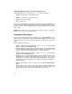
Appendix A Cabling Information This appendix describes the different cable combinations to use for connecting your printer to a host device and includes IBM PC interface programming instructions. A.1 Cable Combinations Table A–1, column 1 lists the host devices that you can connect to your printer. They are grouped by the type of connector they use. The second column lists the part numbers of the adapter and the cable required for each host device.
Table A–1 (Cont.): Cables and Adapters for Communication Connections Connector Type Adapter and Cable Required Connecting Instructions H8571–B and H8571–E1 and BC16E1 Attach the H8571–B (9-pinto-MMJ) adapter to these hosts, then connect one end of the BC16E cable to the H8571– B. Attach the H8571–E adapter to the DEClaser printer, then connect the other end of the BC16E cable to the H8571– E. H8571–E1 and BC16E1 Attach one end of the BC16E cable to one of these hosts.
Table A–1 (Cont.): Cables and Adapters for Communication Connections Adapter and Cable Required Connecting Instructions H8571–J and H8571–E1 and BC16E1 Attach the H8571–J adapter to one of these hosts, then connect one end of the BC16E cable to the H8571–J. Attach the H8571–E adapter to the DEClaser printer, then connect the other end of the BC16E cable to the H8571–E. Use data transmit ready (DTR) flow control. Refer to the DEClaser 1100 Printer Operator’s Guide.
Table A–1 (Cont.): Cables and Adapters for Communication Connections Connector Type Adapter and Cable Required Connecting Instructions BC19M–10 Connect the BC19M–10 to the DEClaser printer and to the host. H8571–C and H8571–E1 and BC16E1 Connect the H8571–C adapter plug to the socket of your printer’s BC22D cable. Connect one end of the BC16E cable to the H8571–C adapter. Attach the H8571–E adapter to the DEClaser printer, then connect the other end of the BC16E cable to the H8571–E.
A.2 Interface Programming Instructions This section describes how to set up an IBM PC to interface with your printer. A.2.1 Serial Flow Control If you are using an IBM PC or compatible and you want to use the optional serial port on your PC, follow these steps: 1. Edit your AUTOEXEC.
If you are using a 25-pin PC/SA with xon/xoff, follow these steps: 1. Edit your AUTOEXEC.BAT file to contain the following two lines: mode com1:4800,n,8,1,-,n mode lpt1:=com1: where: mode com1:4800,n,8,1,-,n specifies that the first serial port (COM1) is used by the printer, that 4800 baud is the communication speed, that no parity is selected, that eight data bits are selected, that one stop bit is used, that the printer tries only once to connect, then time-out, and that the type weight is normal.