INSTALLATION GUIDE DIGITAL Laser Printer LN15 (models LN15P, LN15N-A and LN15N-B) p/n. : EK-LN15E-IG version 1.
Installation Guide DIGITAL Laser Printer LN15
CONTENTS 1. INTRODUCTION------------------------------------------------------------------------------------------4 1.1. GETTING ACQUAINTED------------------------------------------------------------------------4 1.2. PRINTER CONFIGURATIONS-----------------------------------------------------------------5 1.2.1. The DIGITAL Laser Printer LN15P------------------------------------------------------5 1.2.2. The DIGITAL Laser Printer LN15N-A---------------------------------------------------5 1.2.3.
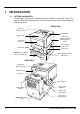
1. INTRODUCTION 1.1. GETTING ACQUAINTED The drawings illustrate the various parts of your DIGITAL Laser Printer LN15. The parts are referred to throughout this manual, so please take some time to become familiar with them.
1.2. PRINTER CONFIGURATIONS The DIGITAL Laser Printer LN15 is available in the following configurations: 1.2.1. THE DIGITAL LASER PRINTER LN15P Standard RAM : 11 Mbyte Standard Resolution : 600 x 600 dpi Standard Paper input : Single-sheet Manual Feeder : 500-sheet (upper) cassette Standard Interfaces : Centronics parallel 1.2.2.
1.3. ABOUT THE DOCUMENTATION This chapter explains the available DIGITAL Laser Printer LN15 documents. The more detailed documentation is on the DIGITAL Laser Printer LN15 CD-ROM in PDF format, included in the shipment of your printer. You may view or print this documentation from your host computer, when needed. • DIGITAL Laser Printer LN15 Installation Guide You are looking at this manual right now.
2. SETTING UP YOUR PRINTER 2.1. UNPACKING THE PRINTER Use the following procedure to unpack the printer. To ensure that your printer was not damaged during shipment, follow the entire procedure. NOTE Save the packing materials of all components and options in case you ever have to move or ship the printer to a new location. 1 Open the box and remove everything except the printer from the shipping carton.
2.2. 5 Remove the restraint card board and tape from the media cassette. 6 Close all covers and place the printer in the location where it is to reside. INSTALLING THE DUPLEXING UNIT (optional) If you did not purchase the optional duplexing unit, please proceed with the next chapter (‘PLACE THE PRINTER’). If you purchased the optional duplexing unit, at this point you should first install the unit. Please refer to the next drawing. DIGITAL Laser Printer LN15P Duplexing Unit Lower Media Tray 1.
3. Temporary remove the rear printer cover. 4. Remove the rear printer stacker by sliding it along the guide grooves in the printer. Store this stacker for future use. It cannot be used when the duplexing unit is installed. 5. Return the rear printer cover into its original place by fixing it with the screw. 6. Before you install the duplexing unit, make sure that the rear part is opened (see drawing).
7. Close the duplexing unit until the lock lever clicks in place. Note that the paper path selector lever has two positions : ‘A’ is the stacker output position and ‘B’ is the duplexer position. NOTE You cannot close the duplexing unit, unless the paper guide is pushed down in the locked position. Carefully check before attempting to close the unit. NOTE Try to push the paper path selector.
2.4. 2. On the left side of the tray, set the lock lever to the open position (see drawing, position ‘B’). 3. Make sure that the rear part of the duplexing unit is locked properly. Lift the printer and duplexing unit by the transport grips of the duplexing unit. Carefully put it on top of the lower media tray, by inserting the two guide pins into the two holes at the bottom of the duplexing unit. The most convenient way is to perform the installation from the front side. 4.
2.5. INSTALLING CONSUMABLES You must install the toner cartridge, load the paper cassette(s), connect the power cord and print a test page before you should install any option. 2.5.1. INSTALLING THE TONER CARTRIDGE 12 1 Remove the Toner Cartridge from its bag. 2 Distribute the toner in the cartridge by moving it back and forth in a horizontal motion several times. 3 Remove the plastic seals from the toner cartridge. Gently pull off the seals, being careful not to spill toner.
6 Lock the Toner Cartridge. Push the Toner Cartridge forward until it clicks into place (the cartridge stands nearly upright when installed correctly). 7 Close the printer’s upper door. Make sure the upper door is locked completely. NOTE Once you have installed the toner cartridge, do not remove it from the printer until it is empty. Removing causes toner to spill into the printer. 2.5.2. INSTALLING THE CLEANER AND CLEANER PAD The printer is shipped with the Cleaner and Cleaner Pad installed.
2 Open the Cleaner Cover, by pushing the engraved portion just before the cover. Lift the front of the Cleaner Cover to completely open it. 3 Install the Cleaner in the printer 4 Lock the Cleaner in place. 5 Close the Cleaner Cover.
2.6. LOADING THE UPPER MEDIA CASSETTE (standard) The cassette of the upper tray may hold max. 500 sheets of media. 1 Pull out and completely remove the cassette. Check if the (green) media size indicator is positioned to the correct media size. 2 In case you need to change the media size of the cassette, follow the next steps. Otherwise, proceed with item 3. A. Change the media size setting by lifting the right end of the green indicator and position its triangle mark to the size required. B.
3 Lock the pressure plate of the cassette. If the front of the pressure plate is raised, push it down until the pressure plate clicks into place. 4 Widen the side guides. While bending both side guides inward, push the guides outward. 5 Load the media. Make sure that the tray is not overloaded. 6 Adjust the side guides. There should be little space left to both sides of the media.
2.7. 7 Arrange the media edges by rocking the cassette to gather the edges of the stack together to ensure correct positioning of the media in the cassette. 8 Return the cassette into the tray. LOADING THE LOWER MEDIA CASSETTE (optional) The cassette of the lower tray may hold max. 450 sheets of media. This cassette differs slightly from the upper cassette. 1 Pull out and completely remove the cassette.
A. Change the media size setting by lifting the right end of the green indicator and position its triangle mark to the size required. B. Adjust the rear media guide by pushing the two catches inward and release the pins from the holes. Then move the rear media guide to the size required (there are media size marks in the cassette). C. Adjust the side guides (there are media size marks in the cassette). D.
2.8. 5 Arrange the media edges by rocking the cassette to gather the edges of the stack together to ensure correct positioning of the media in the cassette. 6 Return the cassette into the tray. LOADING THE MANUAL FEED TRAY The manual feed tray may be used for single sheets. However, you will have to insert one sheet at a time. Usually, the manual feed tray is used for media other than normal, like envelopes, labels and transparencies. 1. Open the front cover. 2.
2.9. USING THE REAR STACKER (standard) The printer has a rear stacker that allows you to eject sheets straight out the back to minimize curl. It is recommended to use the rear stacker, printing envelopes, overhead transparencies and labels. 1 Open the rear stacker. 2 Remove the paper support from inside the stacker. 3 Set the paper support in position. Insert the two ends of the paper support into the mounting grooves of the rear stacker. 2.10.
1 Open the duplexer rear stacker. 2 Open the metal paper support from inside the stacker. 3 Set the paper path selector lever to the stacker position ‘B’ (‘A’ is the duplexer position). NOTE Setting the paper path selector to the stacker position ‘B’ and not opening the stacker, will always result in a paper jam. 2.11. CONNECTING THE POWER CORD 1 Plug the female end of the power cord in the connector on the rear of the printer. Plug the opposite end of the power cord in a grounded AC outlet.
2.13. MESSAGE WINDOW The control panel message window provides status and configuration information. Status messages are listed in chapter 2 of the DIGITAL Laser Printer LN15 User Manual. Printer configuration is also explained in chapter 2 of the DIGITAL Laser Printer LN15 User Manual. The status messages and configuration menus can be displayed in English, French, German, Italian, Spanish or Swedish language. When you receive your DIGITAL Laser Printer LN15 printer, the language is set to English.
2.16. CONNECTING THE PRINTER TO YOUR COMPUTER LN15P The DIGITAL Laser Printer LN15P comes with a Parallel interface (located on the rear side of your printer, see drawing). The DIGITAL Laser Printer LN15N-A and LN15N-B also have an Ethernet interface installed (see drawing). LN15N-A LN15N-B TEST TEST The test button (see drawing) allows you to print an Ethernet interface configuration page (refer to the DIGITAL Laser Printer LN15 Ethernet Interface User Manual).
2.17. THE ETHERNET INTERFACE QUICK CONFIGURATION (optional) 2.17.1. GENERAL CONFIGURATION The server name, printed on the back of the interface, is based on the last six bytes of its unique Ethernet address. Example : LPS_0D242F. You must associate the interface with a service before network users can use the port.
3 Print to the queue lpr - /etc/hosts 2.17.4. WINDOWS NT CONFIGURATION To install a print queue using NetBIOS, please refer to the DIGITAL Laser Printer LN15 Ethernet Interface User Manual. To install print queues using TCP/IP, follow the hext steps: 1 2 3 Install TCP/IP software on the host, if it is not already installed. Using the Windows NT ARP and Ping commands, set the IP address of the interface.
3. THE CONTROL PANEL The control panel, located on the front of the printer, allows you to direct the printer’s operation. In addition, it displays the current status of the printer, including any condition that needs your attention. The control panel consists of the following parts: • Four indicators to provide printer status information. MESSAGE WINDOW • A message window to display status and configuration information.
3.2. CONTROL PANEL KEYS One or two functions are assigned to a key. To use the functions represented by the top labels (a), simply press the button. To use the functions represented by the bottom labels (b), press and hold down the key for more than five seconds. The following table is a brief summary of the function of the keys. Detailed information is available in chapter 2 of the DIGITAL Laser Printer LN15 User Manual. The READY key switches the printer between online and offline.
4. CONTROL PANEL MENU You may use this section as a quick reference for understanding and navigating the menu structure of the DIGITAL Laser Printer LN15. More detailed information is described in chapter 2 of the DIGITAL Laser Printer LN15 User Manual.
5. TROUBLESHOOTING Although the DIGITAL Laser Printer LN15 printers are designed to be highly reliable, you may however, occasionally experience a problem. This chapter helps you to identify the cause of the problem and suggests possible solutions (for English keypad language). For detailed procedures, please refer to the DIGITAL Laser Printer LN15 User Manual available on the DIGITAL Laser Printer LN15 CD-ROM.
STACKER FULL Paper stacker full SYSTEM ERROR n A system error on the controller occurred Paper tray installed incorrectly Toner runs out Replace toner cartridge Printer is ready for manual Insert paper into manual feeder feeder TRAY n MISS SET TONER EMPTY INSERT size Remove paper from paper stacker If the error recurs, consult your dealer for service Install the paper tray properly Paper jams are detected by sensors in the printer and indicated in the message window.
3. Raise the left and right levers of the feed roller (little green handles) and open the paper tray(s). 4. Remove the jammed sheet of paper gently from under the feed roller. 5. Return the two levers to their original positions (pull the levers down toward you) and close the paper tray(s). Install the print unit again and close the top cover. You may now continue printing. WARNING Leaving the two levers raised causes damage to the levers when the print unit is installed. 6. Open the rear stacker.
9. This jam indication appears when a jam occurred in the duplexing unit. Pull out the upper media tray and open the front door of the duplexing unit. 10. Remove the jammed sheet of paper. Close the front door of the duplexing unit and install the upper paper tray. You may now resume your print job. 11. If no jammed paper is visible, open the rear unit of the duplexing unit. 12. Remove the jammed sheet of paper from the rear unit of the duplexing unit. 13. Close the rear part of the duplexer.
6.
Installation Guide DIGITAL Laser Printer LN15
First Printing, November 97 Digital Equipment Corporation makes no representations that the use of its product in the manner described in this publication will not infringe on existing or future patent rights, nor do the descriptions contained in this publication imply the granting of licences to make, use, or sell equipment or software in accordance with the description.
Installation Guide DIGITAL Laser Printer LN15