Service Maintenance Manual MCS LOGISTICS ENGINEERING PRIORIS HX590 & HX590 DP Server K-MN-SD00000-02-JG00.
P R I O R I S H X November 1995 The information in this document is subject to change without notice and should not be construed as a commitment by Digital Equipment Corporation. Digital Equipment Corporation assumes no responsibility for any errors that might appear in this document. The software, if any, described in this document is furnished under a license and may be used or copied only in accordance with the terms of such license.
Digital PRIORIS HX590 & HX590 DP Server Table of Contents Table of Contents PREFACE.............................................................................................................................................................. 7 CHAPTER 1 PRODUCT DESCRIPTION ...................................................................................................... 9 PRODUCT INTRODUCTION ..............................................................................................................
P R I O R I S H X Table of Contents Digital PRIORIS HX590 & HX590 DP Server MAIN LOGIC BOARD JUMPERS ............................................................................................................................. 33 Main Logic Board Jumper Settings................................................................................................................. 33 Main Logic Board Jumper Locations...................................................................................................
Digital PRIORIS HX590 & HX590 DP Server Table of Contents CHAPTER 5 DEVICE MAPPING .................................................................................................................. 67 CPU Memory Address Map (Full Range, 590 CPUs).................................................................................... 67 CPU Memory Address Map (PC Compatibility Range)................................................................................. 68 CPU I/O Address Map.........................
P R I O R I S H X Table of Contents Digital PRIORIS HX590 & HX590 DP Server Table of Figures Figure 2 - 1 SCU Main Menu Options................................................................................................................ 16 Figure 2 - 2 SCU Main Menu Options................................................................................................................ 20 Figure 3 - 1 Unlocking and Removing the Side Panel .................................................................
Digital PRIORIS HX590 & HX590 DP Server Preface H X Preface The Digital PRIORIS HX590 & HX590 DP Server Service Maintenance Manual is a troubleshooting guide that can be used for reference when servicing the PRIORIS HX590 & HX590 DP Server series. Digital Equipment Corporation reserves the right to make changes to the Digital PRIORIS HX590 & HX590 DP Server without notice.
Digital PRIORIS HX590 & HX590 DP Server Chapter 1 Product Description Product Description Product Introduction The PRIORIS HX590 & HX590 DP Servers are a family of high-performance, highly-scalable network and application servers featuring the latest in modular CPU and Storage technology. Developed using the state-ofthe-art technology, PRIORIS HX Servers are the most advanced servers in their class.
P R I O R I S H X Product Description Digital PRIORIS HX590 & HX590 DP Server Product Models Information There are three different system configurations that are currently offered for both single (PRIORIS HX590) as well as dual (PRIORIS HX590 DP) processor servers: Base Systems are built around 16MB (single processor) or 32MB (dual processor) of parity RAM memory and a Fast Wide (16-bit) SCSI host controller.
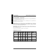
Digital PRIORIS HX590 & HX590 DP Server Product Description PRIORIS HX590 DP Systems Model Memory Cache FDD FR− − 881WW− − AA 32 MB parity 32 MB ECC FR− − 881WW− − AB FR− − 881WW− − AX (1) None (1) HDD 512KB 1.44MB None 512KB 1.44MB 4 x 1GB, SCSI-2 512KB 1.44MB None Host Contr. CD-ROM Adaptec 2940W 1 channel, Wide 1 channel, Narrow RAID, EISA None SCSI-2, 600 KB/sec SCSI-2, 600 KB/sec SCSI-2, 600 KB/sec No memory installed, at least 16MB must be ordered with the system.
Digital PRIORIS HX590 & HX590 DP Server Chapter 2 Utilities & Configuration Server Utilities & Configuration Server Utilities The following sections provide detailed instructions on running the MS-DOS utilities contained on the supplied CD-ROM startup diskette and CD-ROM. Note that these utilities can also be copied to the hard disk drive. Refer to the operating system documentation for information on copying files. PHLASH.
P R I O R I S Utilities & Configuration Digital PRIORIS HX590 & HX590 DP Server Creating a Crisis Recovery Diskette A crisis recovery diskette should always be prepared before attempting to upgrade the BIOS. This diskette is used to reprogram the BIOS in case the flash process fails. To create a crisis recovery diskette: H X 1) 2) 3) 4) 5) 6) Turn on the server and allow the POST to complete. If thePOST detects an error and take the appropriate steps to correct the problem.
Digital PRIORIS HX590 & HX590 DP Server Utilities & Configuration Upgrading The Server's BIOS Perform the following steps to update the server's BIOS in flash memory: 1) 2) 3) 4) Turn on the server and allow the POST to complete. If POST detects an error, take the appropriate steps to correct the problem. After the problem has been resolved, restart the server. Create a crisis recovery diskette. Refer to “Creating a Crisis Recovery Diskette” previously described.
P R I O R I S Utilities & Configuration Digital PRIORIS HX590 & HX590 DP Server The SCU The SCU enables to setup and configure the server using the menu driven items shown in figure 2-1. Depending on the installed hardware and level of server security required, you might have to access one or more of these items to properly configure the server.
Digital PRIORIS HX590 & HX590 DP Server Utilities & Configuration SCI Files and CFG Files The SCU creates a System Configuration Information (SCI) file each time the serverhas been configured. This SCI file can be used on any PRIORIS HX590 (DP) Servers that has been equally configured and can serve as a backup to the EISA configuration stored in NVRAM memory. The SCI file is maintained on the System Configuration Utility diskette and has a default name of SYSTEM.SCI.
P R I O R I S H X Utilities & Configuration Digital PRIORIS HX590 & HX590 DP Server 6) If applicable, set the current server time and date using the Set Time and Set Date menu options. 7) Using the Maintain System Configuration Diskette option, copy the CFG files supplied with any EISA, PCI, or ISA expansion board. 8) Select the Configure Computer option to configure the server. 9) If applicable, select the Maintain System Configuration Diskette option to create, change, or update SCI or CFG files.
Digital PRIORIS HX590 & HX590 DP Server Utilities & Configuration Adding ISA Boards Perform the following steps to add ISA boards to the server configuration: 1) 2) 3) Select "Step 2: Adding and Removing Boards", and update the list of boards and options to include any ISA boards you are going to install in the server. Select "Step 4: Examine Required Switches", to check the required switch and jumper settings of the ISA boards. Select "Step 5: Save and Exit", to save the configuration and exit the SCU.
P R I O R I S H X Utilities & Configuration Digital PRIORIS HX590 & HX590 DP Server SCU Main Menu The SCU enables to set up and configure the server using a menu-driven interface. Depending on the hardware installed in the server and the level of required server security, you might need to access one or more of the menu items to properly configure the server. When accessing the SCU, a welcome screen appears, followed by the main menu options listed below.
Digital PRIORIS HX590 & HX590 DP Server Utilities & Configuration Main Menu Options Menu Fields Settings Comments System time System date Language Current time Current date English Español Français Deutsch Italiano 1.44 MB, 3½ 2.88 MB, 3½ Not Installed 360 KB, 5¼ 1.2 MB, 5¼ 720 KB, 3½ Not installed Displays the current time. Displays the current date. Enables to select a desired language. EGA / VGA CGA 80x25 Monochrome Not user selectable Not user selectable Sets the video controller type.
P R I O R I S H X Utilities & Configuration Digital PRIORIS HX590 & HX590 DP Server Keyboard Features Menu Fields Settings Comments Keyboard features Auto Off On Disabled Enabled 30/sec 2/sec 6/sec 10/sec 13.3/sec 21.8/sec 26.7/sec 1/2 sec 3/4 sec 1 sec 1/4 sec Selects the keyboard option. Key click Keyboard auto-repeat rate Keyboard auto-repeat delay Enables or disables the audible key click feature. Sets the number of times a second to repeat a keystroke while holding the key down.
Digital PRIORIS HX590 & HX590 DP Server Utilities & Configuration Memory and Cache Options (continued) Menu Fields Settings AT bus space Disabled Memory hole not available upper memory is contiguous. F00000h, 1 MB Sets the memory hole at address F00000 with 1 MB memory available. Comments E00000h, 2 MB Sets the memory hole at address E00000 with 2 MB memory available. C00000h, 4 MB Sets the memory hole at address C00000 with 4 MB memory available.
P R I O R I S H X Utilities & Configuration Digital PRIORIS HX590 & HX590 DP Server Integrated Peripherals Menu Fields Settings Comments Mouse port Disabled Enabled 378, IRQ7 278, IRQ5 Auto Disabled 3BC, IRQ7 EPP 1.7 Enables or disables the mouse port. EPP 1.9 Sets the extended capabilities port mode. ECP Compatible mode Compatible mode - standard printer connection.
Digital PRIORIS HX590 & HX590 DP Server Utilities & Configuration Advanced Chipset Control Menu Fields Settings Comments CPU to PCI posting PCI to memory posting CPU to memory posting PCI burst write PCI arbiter Disabled Enabled Enabled Disabled Enables or disables the CPU to PCI write buffers. When enabled, these buffers temporarily store data between writes. Enables or disables the PCI to DRAM write buffers. When enabled, these buffers temporarily store data between writes.
Digital PRIORIS HX590 & HX590 DP Server Chapter 3 Service Procedures Service Procedures Safety Requirements WARNING Static electricity collects on non-conductors such as paper, cloth, or plastic. A static discharge can be damaging even though you often cannot see or feel it.
P R I O R I S The following tools will be needed for servicing Digital PC systems. Note that test equipment must be calibrated: H X ♦ ♦ ♦ Service Procedures Digital PRIORIS HX590 & HX590 DP Server Recommended Tools Multimeter (4 1/2 digit) A Philips screwdriver An antistatic wrist strap Other Needed Materials Cleaning agent should be an all purpose cleaner that is used in-house. Required Special Tools None.
Digital PRIORIS HX590 & HX590 DP Server Service Procedures Removing the Side Panel Before removing the side panel, perform the following: 1) 2) 3) 4) Turn off power to all external devices connected to server. Turn server off. Unplug power cord from wall outlet. Disconnect power cord and monitor cord from server. H X WARNING You might injure yourself or damage the server if you attempt to remove the side panel before unplugging the ac and monitor power cords.
P R I O R I S H X Service Procedures Digital PRIORIS HX590 & HX590 DP Server Server Components (Left Side) Legend Component A B C D E F G H I J K L M N O P Q Operator control panel (OCP) 6 EISA expansion slots Primary PCI 32-bit local bus expansion slots CPU module Main logic board Memory module 3½-inch diskette drive Front access 5¼-inch half-height drive bays CD-ROM drive bay Integral hot-swap device bay (slots 0 through 6 from top to bottom) Cooling fans (two spare fans) Contact switch Power, OCP,
Digital PRIORIS HX590 & HX590 DP Server Service Procedures Server Components (Right Side) Legend Component A B C D E F G H I J K L Power supply Redundant power supply area Storage backplane Contact switch Ac power plug Monitor plug SCSI knockouts (back panel) Keyboard and mouse ports Serial ports Parallel port Video port Keylock H X L G G H J K G C I A F D E B DEC00438-2 Figure 3 - 3 Server Components (Right Side) MCS Logistics Engineering - Nijmegen P R I O R I S 31
P R I O R I S H X Service Procedures Digital PRIORIS HX590 & HX590 DP Server Expansion Slots The PRIORIS HX Server contains 12 expansion board slots. Six of the slots support industry-standard 32-bit EISA expansion boards. The remaining six expansion slots support 32-bit PCI local bus expansion boards. This enables the server to deliver maximum performance by using a faster data path for greater computing speed. It also improves the expandability of the server.
Digital PRIORIS HX590 & HX590 DP Server Service Procedures Main Logic Board Jumpers Jumper pins allow to set specific server parameters. They are set by changing the pin location of jumper blocks. A jumper block is a small plastic-encased conductor (shorting plug) that slips over the pins. Place the jumper over the two pins designated for the desired setting. Press the jumper evenly onto the pins. Be careful not to bend the pins.
P R I O R I S Service Procedures Digital PRIORIS HX590 & HX590 DP Server Main Logic Board Jumper Locations.
Digital PRIORIS HX590 & HX590 DP Server Service Procedures Computer Memory Configurations The server will support up to 512 MB of parity memory and 256 MB of ECC memory using SIMM sockets 0 through 7. When adding additional memory make sure to: ♦ ♦ ♦ ♦ ♦ ♦ Install 36-bit SIMMs having an access time of 70 ns or less. Fill two sockets at a time using the same SIMM size, type, and speed (4 MB, 8 MB, 16 MB, 32 MB, and 64 MB densities are available for parity memory.
P R I O R I S H X Service Procedures Digital PRIORIS HX590 & HX590 DP Server Memory Configurations (continued) Bank 0/1 Bank 2/3 Bank 4/5 2 x 8 MB 2 x 16 MB 2 x 16 MB (ECC) 2 x 16 MB 2 x 16 MB (ECC) 2 x 4 MB 2 x 8 MB 2 x 16 MB 2 x 16 MB (ECC) 2 x 32 MB 2 x 32 MB (ECC) 2 x 64 MB 2 x 4 MB 2 x 4 MB 2 x 8 MB 2 x 8 MB 2 x 4 MB 2 x 16 MB 2 x 16 MB 2 x 8 MB 2 x 32 MB 2 x 32 MB (ECC) 2 x 32 MB 2 x 16 MB 2 x 32 MB 2 x 32 MB 2 x 32 MB (ECC) 2 x 4 MB 2 x 8 MB 2 x 32 MB 2 x 32 MB 2 x 64 MB 2 x 8 MB 2 x 16 MB 2 x
Digital PRIORIS HX590 & HX590 DP Server Service Procedures PRIORIS HX590 & HX 590 DP SIMM Locations P R I O R I S H X Bank 0 Bank 1 Bank 2 Bank 3 Bank 4 Bank 5 Bank 6 Bank 7 Figure 3 - 6 Memory Module MCS Logistics Engineering - Nijmegen 37
P R I O R I S H X Service Procedures Digital PRIORIS HX590 & HX590 DP Server Part Removal and Replacement Procedures Removing the 3½-inch Diskette Drive To remove the 3½-inch diskette drive: 1) 2) 3) 4) 5) 6) Turn off the computer. Disconnect external devices, ac power, and monitor power. Unlock and remove side panels. Disconnect power and ribbon cables. Remove screws securing the diskette drive to chassis. Slide the diskette drive out of the drive bay.
Digital PRIORIS HX590 & HX590 DP Server Service Procedures Removing the CD-ROM Drive To remove the CD-ROM drive: 1) 2) 3) 4) 5) 6) Turn off the computer. Disconnect external devices, ac power, and monitor power. Unlock and remove side panels. Disconnect power and ribbon cables. Remove screws securing the CD-ROM drive to chassis. Slide the CD-ROM drive out of the drive bay.
P R I O R I S H X Service Procedures Digital PRIORIS HX590 & HX590 DP Server Remove the CPU Module To remove the CPU module: 1) 2) 3) 4) 5) 6) 7) Turn off the server. Disconnect external devices, ac power, and monitor power. Unlock and remove left side panel. Remove CPU module retaining bracket. Carefully remove CPU module from main logic board. Replace CPU module and retaining bracket. Replace and lock left side panel. NOTE 8) The server will not operate with the side panel removed.
Digital PRIORIS HX590 & HX590 DP Server Service Procedures Replacing the CPU Chip The CPU module is equipped with a two upgradeable ZIF sockets capable of supporting future higher performance Pentium processors. CAUTION When replacing the CPU make sure the new chip is a 5V device. If only 3.3V devices are available see “To set CPU voltage to 3.3V”. To replace the CPU: 1) 2) 3) 4) 5) 6) 7) Remove the CPU module. Place the CPU module on an anti-static surface.
P R I O R I S H X Service Procedures Digital PRIORIS HX590 & HX590 DP Server CPU Module Jumper Settings Feature Description Setting CPU core/bus frequency ratio 2/1 speed bus 3/2 speed bus J4, jumpered J4, open(1) Reserved Factory use only J8, jumpered(1) J8, open (1) Factory default setting Set the CPU voltage to 3.3V 1) 2) Remove the 5V Jumper Module form the 5V connector J100 on the CPU Module. Push the 3.3 V Jumper Module on the pins of 3.3V connector J101 on the CPU Module.
Digital PRIORIS HX590 & HX590 DP Server Service Procedures Remove the Memory Module To remove the memory module: 1) 2) 3) 4) 5) 6) 7) 8) 9) Turn off the server. Disconnect external devices, ac power, and monitor power. Unlock and remove left side panel. Remove memory module retaining bracket. Carefully remove memory module from main logic board. Install a higher performance memory module or add additional server memory on existing memory module. Replace memory module retaining bracket.
P R I O R I S H X Service Procedures Digital PRIORIS HX590 & HX590 DP Server Removing the Main Logic Board To remove the main logic board: 1) 2) 3) 4) 5) 6) Turn off the computer. Disconnect external devices, ac power, and monitor power. Unlock and remove side panels. Remove all connectors. Remove all expansion boards. Remove screws and lift the board out.
Digital PRIORIS HX590 & HX590 DP Server Service Procedures Removing the Power Supply To remove the Power Supply: 1) 2) 3) 4) 5) 6) 7) 8) Turn off the server. Disconnect external devices, ac power, and monitor power. Unlock and remove left side panel. Remove metal shield. Remove screws securing power supply to rear of chassis. Release power supply from two locking tabs at side of chassis. Carefully remove power supply from server. Replace and lock left side panel.
P R I O R I S H X Service Procedures Digital PRIORIS HX590 & HX590 DP Server Removing the Optional Power Supply To remove the Optional Power Supply: 1) 2) 3) 4) 5) 6) 7) 8) Turn off the server. Disconnect external devices, ac power, and monitor power. Unlock and remove left side panel. Remove metal shield. Remove screws securing power supply to rear of chassis. Release power supply from two locking tabs at side of chassis. Carefully remove power supply from server. Replace and lock left side panel.
Digital PRIORIS HX590 & HX590 DP Server Service Procedures Replacing Secondary Cache Memory The CPU module comes with standard or burst secondary cache memory in the form of a single in-line cache module. Secondary cache memory is designed to greatly improve the performance of the installed CPU(s). Note that “standard” cache refers to asynchronous cache and “burst” cache to synchronous (higher performance) cache. H X To replace secondary cache memory: 1) 2) 3) Remove the CPU module.
P R I O R I S H X Service Procedures Digital PRIORIS HX590 & HX590 DP Server Replacing a Device Into the Hot-Swap Drive Bay Hot-swapping allows to remove or install an SBB (Storage Building Block) while the server remains online and active, eliminating interference with the server's operation. For SBBs, the hot-swap method can be used to replace a device providing that the device is not active (green activity LED is off). Refer to the next section “SBB LED Status Indicators”.
Digital PRIORIS HX590 & HX590 DP Server Service Procedures SBB LED Status Indicators The hot-swap backplane monitors shelf status to identify error conditions or failures. This status is displayed on the SBB LEDs. The left LED displays the device activity and the right LED displays the fault status. ♦ The left LED (green) is the device activity LED and is on or flashing when the SBB is active.
P R I O R I S H X Service Procedures Digital PRIORIS HX590 & HX590 DP Server Replacing the Server Battery/Real Time Clock (RTC) The server's battery runs the server clock and retains any setup information when it is turned off. If the server ever fails to retain the correct date, time, or configuration settings when it is turned on, you need to replace the server's battery. To replace the battery, perform the following: 1) 2) 3) 4) 5) 6) 7) 8) 9) Record server configuration settings using the SCU.
Digital PRIORIS HX590 & HX590 DP Server Service Procedures Connecting SCSI devices The server supports up to 10 internal SCSI devices. Additional SCSI devices can be added to the server by using an EISA- or PCI-based SCSI host adapter installed in an available expansion slot in conjunction with an external SCSI expansion box. The storage backplane supports seven hot-swap devices split between two SCSI bus sections, SCSI bus A and SCSI bus B.
P R I O R I S H X Service Procedures Digital PRIORIS HX590 & HX590 DP Server SCSI Drive IDs SCSI bus device addresses are automatically assigned in the hot-swap drive bay depending on the slot number in which they are installed. The address jumper on the storage backplane is used to override the default addresses. The default settings are listed in the following table and can be set manually to different addresses at the option.
Digital PRIORIS HX590 & HX590 DP Server Service Procedures Using Multiple or Multi-Channel SCSI Host Adapters The following guidelines apply when configuring the server using multiple or multi-channel SCSI host adapters: ♦ ♦ ♦ ♦ The SCSI host adapter with the lowest BIOS address is identified by the server as the "primary" SCSI host adapter. When loading the operating system from a SCSI hard disk drive, this primary or boot drive must be connected to the primary SCSI host adapter.
P R I O R I S H X Service Procedures Digital PRIORIS HX590 & HX590 DP Server Single Channel SCSI Bus - Legend Legend Component A B C D E F SCSI host adapter (ID7, channel A, host termination) 68-pin-to-50-pin adapter cable to CD-ROM 68-pin-to-50-pin adapter cable to top-right drive bay Backplane, 68-pin connector Terminator Jumper cable NOTE This terminator can be removed and replaced with a 68-pin wide cable to connect to an external SCSI device.
Digital PRIORIS HX590 & HX590 DP Server Service Procedures Connecting a Dual Channel SCSI Bus To connect SCSI devices to a dual channel adapter, perform the following: 1) 2) 3) 4) 5) Connect the 68-pin SCSI cable connector to the SCSI host adapter. Connect the SCSI cables as shown in the illustration. If necessary, connect appropriate power cable to device. Replace and lock side panels. Connect external devices and restore power.
P R I O R I S H X Service Procedures Digital PRIORIS HX590 & HX590 DP Server External SCSI Bus additional SCSI cables and/or host adapters can be used to connect external SCSI devices to the server. To connect the storage backplane to an external SCSI bus: 1) 2) 3) 4) 5) Remove the terminator from the storage backplane for the bus you want to connect. Connect the 68-pin unshielded cable connector to the storage backplane (A).
Digital PRIORIS HX590 & HX590 DP Server Chapter 4 Troubleshooting Troubleshooting The following pages provide initial troubleshooting procedures and tables listing specific problems, probable causes, and recommended actions to take if the computer fails after configuring it or after installing optional hardware or software. Refer to the documentation supplied with additional options when experiencing problems with specific installed options.
P R I O R I S H X Digital PRIORIS HX590 & HX590 DP Server Troubleshooting Beep Codes When POST finds an error and cannot display a message, the server's speaker emits a series of beeps to indicate the error. During POST, if the video configuration fails or if an external ROM module fails a checksum test, then the server beeps three times.
Digital PRIORIS HX590 & HX590 DP Server Troubleshooting POST and Boot Messages (continued) Message Description/Solution Where nnnn is the amount of server cache (in kilobytes) that tested successfully. Run the SCU. Check all connections. If the problem persists-replace the Diskette drive A error diskette drive. Diskette drive B error SCU runs. Entering SETUP Extended RAM Failed at offset: Extended memory failed or configured incorrectly. Make sure SIMMs are installed correctly.
P R I O R I S H X Digital PRIORIS HX590 & HX590 DP Server Troubleshooting POST and Boot Messages (continued) Message Description/Solution nnnn Shadow RAM passed Where nnnn is the amount of shadow RAM (in kilobytes) that tested successfully. Replace the battery and then run the BIOS Setup utility to restore previous configuration information. This indicates that the servers BIOS was successfully copied to shadow RAM. RAM cache failed. Run the SCU and restore all settings to original values.
Digital PRIORIS HX590 & HX590 DP Server Troubleshooting Server Troubleshooting Problem Possible Cause Action No response when the server is on Main logic board failed. Replace the failed component. Main logic board jumpers incorrectly set. Set all appropriate jumpers. CPU module has failed. Replace the failed component. CPU module jumpers incorrectly set. Make sure the jumpers are correctly set. No memory module or SIMMs installed. Install SIMMs and memory module. Side panels removed.
P R I O R I S H X Digital PRIORIS HX590 & HX590 DP Server Troubleshooting Server Troubleshooting (continued) Problem Possible Cause Action Server operates incorrectly after installing optional memory (SIMMs) on the memory module SIMMs installed incorrectly. Remove SIMMs and reinstall. SIMMs have failed. Replace SIMMs. Memory module installed incorrectly. Reinstall memory module.
Digital PRIORIS HX590 & HX590 DP Server Troubleshooting Disk Drive Troubleshooting Problem Possible Cause Action Server does not recognize an internal or external SCSI device SCSI device jumpers incorrectly set. Correct SCSI jumper setting. SCSI ID conflicts. Refer to SCSI ID settings in Chapter 3. H X Terminating resistors not removed Remove terminating resistors. from the SCSI device. Server does not boot from an internal SCSI hard disk drive SCSI host adapter has failed.
P R I O R I S H X Digital PRIORIS HX590 & HX590 DP Server Troubleshooting CD-ROM Troubleshooting Problem Possible Cause Install correct device drivers. Cannot access the CD-ROM Accessing wrong drive. drive. Error message reading drive X Disc is spinning Application software not running. but drive is idle Action Device drivers not installed. Make sure correct SCSI ID is assigned. Run application software.
Digital PRIORIS HX590 & HX590 DP Server Troubleshooting Monitor Troubleshooting (continued) Problem Possible Cause Action Monitor display not centered while loading Windows video drivers Monitor type incorrectly set. Set the correct monitor type. Refer to appropriate video driver documentation. H X QAPlus/FE Advanced Diagnostics Run QAPlus/FE Advanced Diagnostics to: ♦ ♦ ♦ ♦ Receive system Information, select SysInfo menu from the main menu.
P R I O R I S H X Digital PRIORIS HX590 & HX590 DP Server Troubleshooting QAPlus/FE Error Messages (continued) Component Messages Solution Battery/clock Clock Stopped Invalid Date RTC Interrupt Failed CMOS Clock Test Failed COM port failed Run Setup Replace battery/clock Change time from Setup menu in QAPLUS Check COM device Serial Chip Error Check connections Serial Compare Error Replace COM device Serial Time-out Error Video Failed Replace COM device Replace video adapter Error in Video Buf
Digital PRIORIS HX590 & HX590 DP Server Devic Mapping Chapter 5 Device Mapping This section provides a series of tables listing mapping and address information related to computer memory and various main logic board devices (keyboard controller, interrupt controller, DMA controller, etc.). The computer's memory and address locations are allocated at the factory to operate within a standard PC environment.
P R I O R I S H X Devic Mapping Digital PRIORIS HX590 & HX590 DP Server CPU Memory Address Map (PC Compatibility Range) Address Range Function Size 00000 to 7FFFF 80000 to 9FFFF A0000 to BFFFF Main memory Main/PCI/ISA memory PCI/ISA video buffer memory Video memory BIOS PCI/ISA card BIOS and buffer memory ISA/PCI adapter RAM after POST completes Used by BIOS Setup during POST SCSI BIOS (if enabled) System BIOS memory 512 KB 128 KB 128 KB C0000 to C7FFF C8000 to DFFFF E0000 to EBFFF EC000 to EFFFF
Digital PRIORIS HX590 & HX590 DP Server Devic Mapping I/O Address Map Range (hexadecimal) Function 060 to 064 0F0 to 0FF 1F0 to 1F7 278 to 27F 2F8 to 2FF 378 to 37F 3BC to 3BE 3F0 to 3F7 3F8 to 3FF Keyboard/mouse controller Math co-processsor IDE controller (if enabled) LPT2 (if enabled) COM2 (if enabled) LPT1 (if enabled) LPT3 (if enabled) Diskette controller (if enabled) COM1 (if enabled) H X PCI Configuration Space Address Map Range (hexadecimal) Function C0xx C1xx C2xx C6xx C7xx C8xx CPU bridg
Digital PRIORIS HX590 & HX590 DP Server Chapter 6 Pass / Fail Criteria Pass / Fail Criteria As Final Acceptance Test’ the following tests should be run to meet the Pass/Fail criteria: 1) Successful completion of the POST tests.
Digital PRIORIS HX590 & HX590 DP Server Appendix A Service Notes Service Notes Recommended Tools The following tools will be needed for servicing Digital PC systems. Note that test equipment must be in calibration. ♦ Multimeter (4 1/2 digit) ♦ A philips screwdriver ♦ An antistatic wrist strap Other Needed Materials Cleaning agent should be an all purpose cleaner that is used in-house. Required Special Tools. None. Remedial Diagnostic Test Software.
P R I O R I S H X Service Notes Digital PRIORIS HX590 & HX590 DP Server ECO/FCO Information. BIOS version information. Refer to the Digital DECpc Bulletin Board Support , for the latest information on BIOS upgrades Network locations: North America, South America, Australia and New Zealand: PCBUHD::DKB300:[WC30.BBSFILES] Europe, Africa, Middle and Far East: SUTRA::D6:[PUBLIC].
Digital PRIORIS HX590 & HX590 DP Server Appendix B Useful Information Useful Information Related documentation Document Titles Order #’s Prioris HX Server Quick Reference Guide Prioris HX Server User’s Guide Prioris HX Server Quick Setup Guide Prioris HX Server System & Options Configuration Guide Pentium CPU Modules Pentium CPU Modules (Multilingual) Quick Reference Guide, Spares Catalogue Sevice Maintenance Manual, Spares Catalogue EK-A0825-RG ER-880WW-UA ER-880WW-IA ER-880WW-CA ER-78XWW-CA ER-78XW
Digital PRIORIS HX590 & HX590 DP Server Document Feedback H X Document Feedback If you have comments on the contents or layout of this document we highly appreciate you feedback. We will do our best to make this document a valuable support to your service effort for Digital. Please fill -out the reader feedback form and send or fax it to: Digital Equipment Parts Center b.v. Att: MCS Logistics Engineering Call Desk P.O.
Personal Notes
Personal Notes
Personal Notes
Personal Notes
READERS COMMENTS Digital PRIORIS HX590 & HX590DP Server Service Maintenance Manual EK-A0816-SV REV A01 This form is for documents only. Commitments submitted on this form are used at Digital’s direction. Did you find errors in this manual? If so, specify by page. .................................................................................................................................................................................... ...................................................................