TSZ07 Tape Drive digi tal Installation/Owner’s Manual Order Number: EK–TSZ07–IN–003
TSZ07 Tape Drive Installation/Owner’s Manual Order Number: EK–TSZ07–IN–003 Prepared by Information Design and Consulting Digital Equipment Corporation • Merrimack, NH 03054
September 1992 The information in this document is subject to change without notice and should not be construed as a commitment by Digital Equipment Corporation. Digital Equipment Corporation assumes no responsibility for any errors that may appear in this document. No responsibility is assumed for the use or reliability of software on equipment that is not supplied by Digital Equipment Corporation or its affiliated companies. Restricted Rights: Use, duplication, or disclosure by the U.S.
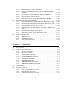
Contents Preface vii Chapter 1 Description 1.1 1.2 Introduction . . . . . . . . . . . . . . . . . . . . . . . . . . . . . . . . . . . . . . . . . . 1–1 Description . . . . . . . . . . . . . . . . . . . . . . . . . . . . . . . . . . . . . . . . . . . 1–1 Chapter 2 Installation 2.1 2.2 2.3 2.4 Introduction . . . . . . . . . . . . . . . . . . . . . . . . . . . . . . . . . . . . . . . . . . 2–1 Site Preparation . . . . . . . . . . . . . . . . . . . . . . . . . . . . . . . . . . . . . . .
2.4.5 2.4.6 2.5 2.6 Installing the Cabinet Stabilizer . . . . . . . . . . . . . . . . . . Remove Packing Material from the TSZ07-BA/BB, -EA/EB . . . . . . . . . . . . . . . . . . . . . . . . . . . . . . . . . . . . . . 2.4.7 Opening the Cabinet TSZ07, Alternate Method . . . . . . . 2.4.8 Unpacking the Small Carton . . . . . . . . . . . . . . . . . . . . . 2.4.9 Installing Cables on the TSZ07-BA/BB, -EA/EB . . . . . . Installing Rackmountable Models . . . . . . . . . . . . . . . . . . . . . . . . 2.5.
3.5 3.6 3.7 3.8 3.4.4 User Density Selection . . . . . . . . . . . . . . . . . . . . . . . . . . . 3–7 Activity Messages . . . . . . . . . . . . . . . . . . . . . . . . . . . . . . . . . . . . . 3–7 Automatic Tape Loading . . . . . . . . . . . . . . . . . . . . . . . . . . . . . . . . 3–8 3.6.1 Manual Tape Loading . . . . . . . . . . . . . . . . . . . . . . . . . . 3–11 3.6.2 Loading High-Static Tape . . . . . . . . . . . . . . . . . . . . . . . 3–14 Unloading Tape Automatically . . . . . . . . . . . . .
2–14 2–15 2–16 3–1 3–2 3–3 3–4 3–5 4–1 4–2 Opening Cabinet Lid . . . . . . . . . . . . . . . . . . . . . . TSZ07 Cover Retaining Arm - Rackmount Model Rack Mounting the TSZ07 . . . . . . . . . . . . . . . . . . Front Panel . . . . . . . . . . . . . . . . . . . . . . . . . . . . . Write Enable Ring . . . . . . . . . . . . . . . . . . . . . . . . Inserting the Tape Reel . . . . . . . . . . . . . . . . . . . . Location of the Manual Release Switch . . . . . . . . Tape Path . . . . . . . . . . . . . . . . . .
Preface This manual provides the information needed to install and operate the TSZ07 Tape Drive. Structure of this Manual The manual consists of the following chapters and appendices: Chapter 1, System Overview – Includes a general description of the system and its components, and explains the system features. It also lists the available system variations. Chapter 2, Unpacking and Installing – Explains how to prepare the site and how to unpack, install, and configure the system.
Related Documentation • KZQSA Module Installation Guide (EK-KZSQA-IG) • MicroVAX Diagnostic Monitor User’s Guide (AA-FM7AE-DN) • TSZ07 Tape Drive Technical Manual (EK-TSZ07-TM) • TSZ07 Tape Drive Pocket Service Guide (EK-TSZ07-PG) • H9642 Cabinet Maintenance Guide (EK-187AA-MG) • Site Environmental Preparation Guide (EK-CSEPG-MA) Notes, Cautions, and Warnings Where notes, cautions, and warnings are used in this document, specific types of information are highlighted as follows: NOTE – Calls the
ix
Für Bundesrepublik Deutschland und Berlin (West) For Federal Republic of Germany und West Berlin Pour la République féderale d’Allemagne et Berlin Ouest Hochfrequenzgerätezulassung und Betriebsgenehmigung Bescheinigung des Herstellers/Importeurs Hiermit wird bescheinigt, daß die Einrichtung in Übereinstimmung mit den Bestimmungen der DBP-Berfügung 523/1969, Amtsblatt 113/1969, und Grenzwertklasse "A" der VDE0871, funkentstört ist.
Kennzeichnung Die Geräte werden bereits in der Fertigung mit der Zulassungsnummer gekennzeichnet und mit einer Anmeldepostkarte versehen. Sollte Kennzeichnung und Anmeldepostkarte übergangsweise nicht mit ausgeliefert werden kontaktieren Sie bitte das nächstgelegene Digital Equipment Kundendienstbüro.
Figure 1: Models of TSZ07 xii
Chapter 1 Description 1.1 Introduction This chapter contains a brief description of the TSZ07 Tape Drive. Figure 1 shows the available models. 1.2 Description The Digital TSZ07 Tape Drive is a high-capacity streaming half-inch tape drive for data interchange, archival storage, software distribution, online transaction management, and backup for small and large computing systems.
have a lower load reliability (85%) than the larger reels (98%) for ANSI compatible tapes. Any reel with less than 600 feet of tape may require manual loading (the 6-inch reel holds 600 feet). The TSZ07 requires at least 300 feet of tape on the reel to operate.
Chapter 2 Installation 2.1 Introduction This chapter explains how to unpack, install, and configure the tape drive. There are three unpacking procedures: • Cabinet Models (TSZ07-BA/BB, -EA/EB) • Table Top Models (TSZ07-CA, -FA) • Rackmountable Models (TSZ07-AA, -DA) TSZ07 models with -BA/BB, -CA, and -AA designations are single-ended drives. TSZ07 models with -EA/EB, -FA, and -DA designations are differential drives.
2.2 Site Preparation No special site preparation is required, although peripherals operating in office areas can be affected by static discharge, temperature changes, and extremes of humidity. These conditions may cause poorer operation and decrease the dependability of the TSZ07 Tape Drive. Good site planning will decrease these effects and ensure dependable operation.
If anything is missing, damaged, or incorrect, contact the dealer from whom the equipment was ordered. Remove any tape securing the front door (see Figure 2-1). The TSZ07 is shipped with a plastic packing ring on the take up hub which must be removed before it can be operated. To remove the packing ring, place the TSZ07 in the tape access position, as described in the following section.
2.3.2 Removing Packing Material from the TSZ07-CA, -FA To place the TSZ07 in the tape access position, perform the following: NOTE Step 1 applies to early versions of the TSZ07 which have latches that engage the top cover. If these latches are not present, proceed to step 2. 1. Push down on the top front corners (see Figure 2–2) to disengage the latch, then lift the enclosure lid.
2. Raise the top cover and place the cover retaining arm in the recess next to the tape path. See Figure 2–3.
You can now remove the packing ring from the take-up hub. To close the table top TSZ07 enclosure, perform the following: 1. Lift the cover retaining arm (see Figure 2–3). 2. Close the top cover of the tape drive. 3. Close the enclosure lid by releasing the latch (see Figure 2–2), closing the lid, and pushing down on the top front corners of the enclosure lid until the latch engages. 2.3.3 Unpacking the Accessories Carton Open the accessories carton and remove its contents.
CAUTION Single-ended and differential SCSI busses require different termination. Be sure to use the terminators marked "differential" with the differential drive (the terminators are supplied with the drive). Figure 2–4: TSZ07 Rear Panel Supported SCSI bus configurations for the TSZ07 Tape Drive are shown in Figures 2-5 and 2-6.
Figure 2–5: Typical Standalone SCSI Configurations DECstation 2100 DECstation 3100 * DECstation 3100 BC56H–06 OR BC56H–03 (0.91m) VAXstation 3100 * TSZ07 ** BC06P–xx MicroVAX 3100 TSZ07 (0.91m) Q–bus BASED VAXsystem BC06P–xx KZQSA ADAPTER (0.91m) ** TSZ07 VAXBI BASED SYSTEM ** BC13N–25 KZBSA ADAPTER TSZ07 *** * INTERNAL SCSI BUS TERMINATOR (P/O SCSI MSC MODULE).
Figure 2–6: Typical Daisy Chained SCSI Configurations DECstation 2100 DECstation 3100 DECsystem 3100 VAXstation 3100 BC56H–03 * SCSI DEVICE (0.91m) BC06P–XX TSZ07 ** BC06P–XX MicroVAX 3100 * SCSI DEVICE (0.91m) BC06P–XX TSZ07 ** Q–bus BASED VAXsystem KZQSA ADAPTER BC06P–XX SCSI DEVICE (0.91m) TSZ07 ** * INTERNAL SCSI BUS TERMINATOR (P/O SCSI MSC MODULE).
Additional technical information on the interface and the connectors is available in the Module Installation Guide (see the Related Documentation section). The ideal cable impedance match with terminators is 132 ohms. A characteristic impedance of 100 ohms 10% is recommended for unshielded flat or twisted-pair cables; a characteristic impedance greater than 90 ohms is preferred for shielded cables. Cables of different impedances should not be used. A minimum conductor size of 28 AWG is required.
2.4 Installing the Cabinet Models (TSZ07-BA/BB, -EA/EB) Installation of the Cabinet TSZ07 requires the following: 1. Unpacking the TSZ07. 2. Unpacking the accessories box. 3. Installing the cables. When these procedures are complete you can operate the TSZ07 (see Chapter 3 for operating information). 2.4.1 Unpacking The Cabinet Models (TSZ07-BA/BB, -EA/EB) The TSZ07-BA/BB and TSZ07-EA/EB cabinet models are shipped in one skid mounted carton (see Figure 2–7) and two smaller cartons.
Figure 2–7: Cabinet Carton Removal 2–12 Installation
2.4.2 Tools and Working Space The following tools are required for unpacking the cabinet model TSZ07. • Scissors • 9/16-inch wrench • 11/16-inch wrench • 3/4-inch wrench • 5/32-inch hex key Also, a space of approximately 3 meters (10 feet) on each side is required for moving the cabinet off of the shipping skid (see Figure 2–8).
2.4.3 Removing the TSZ07-BA/BB, -EA/EB from the Carton Use the following procedure to remove the cabinet model from the carton. WARNING Once the leveling feet are raised, the cabinet is free to roll on its casters. The cabinet is top heavy and must be handled with care. 1. Cut the nylon straps and remove the corrugated cardboard box (see Figure 2–7). 2. Using a 9/16-inch wrench, remove the four shipping bolts that hold the cabinet to the skid. Figure 2–9 shows the sequence in which to unpack the unit.
Figure 2–9: Unpacking Sequence 3. Remove the metal hold-down brackets.
4. Using a 11/16-inch wrench, loosen the leveling feet locking nuts (see Figure 2–10). Figure 2–10: Raising Leveling Feet 5. Using a 9/16-inch wrench, screw the leveling feet up into the cabinet base all the way. 2.4.4 Removing the Cabinet from the Skid Use the following procedure to remove the cabinet from the skid. WARNING Use sufficient manpower to move the cabinet off of the skid. 1. Install ramps onto the pallet deck.
2. Grasp the cabinet by the right top and left top (see Figure 2–11).
3. Roll the cabinet off of the skid and down the ramps, taking care to prevent it from tipping over. 4. Open the rear door using a 5/32 inch hex key (see Figure 2–12) and verify that the accessory kit is present.
2.4.5 Installing the Cabinet Stabilizer The cabinet model TSZ07 is shipped with a stabilizer in the top of the packing carton. This stabilizer should be used for installations where the cabinet is free standing (not connected to other cabinets). To install the stabilizer on the cabinet model TSZ07 perform the following: 1. Remove the cardboard protectors from the ends of the cast stabilizer. 2.
8. Place lock washer and the rectangular washer on the 1/2 x 3/4 hex screw and thread the screw into the coupler. 9. Slide the shim into place. 10. Level the cabinet by adjusting the couplers. • To raise the cabinet, turn the coupler counterclockwise. • To lower the cabinet, turn the coupler clockwise. 11. Tighten the 1/2 x 3/4 hex screw, using a 13/16 inch box wrench, to 250 inch pounds. Insert a screwdriver in the 5/16 hole in the side of coupler to hold it for tightening. 12.
Figure 2–13: Installing the Cabinet Stabilizer Installation 2–21
2.4.6 Remove Packing Material from the TSZ07-BA/BB, -EA/EB When you receive the TSZ07 there is a plastic ring on the takeup hub which must be removed before operating the TSZ07. To access the tape path, perform the following: 1. Lift the lid on the cabinet until the lid latch locks it in place (see Figure 2–14). 2. Raise the top cover of the TSZ07 and place the cover retaining arm in the recess next to the tape path (see Figure 2–14).
Figure 2–14: Opening Cabinet Lid Installation 2–23
You can now remove the packing material from the take-up hub (see Figure 2–3). To close the TSZ07 cabinet enclosure, perform the following: 1. Lift the cover retaining arm. 2. Close the top cover of the TSZ07. 3. Close the cabinet lid by releasing the latch and placing the lid in the closed position. 2.4.
2.4.8 Unpacking the Small Carton Open the accessories box and check its contents.
2.5.1 Unpacking Rackmountable Models (TSZ07-AA, -DA) The rackmountable models are shipped in one large carton and one smaller carton. The large carton contains the TSZ07 tape transport cabinet. The smaller carton contains documentation, a cleaning kit, a SCSI cable, a power cord, and a reel of magnetic tape. A SCSI terminator is mounted on the rear of the TSZ07. Hardware for rack-mounting the tape drive is also included. CAUTION Single-ended and differential SCSI busses require different termination.
Figure 2–15: TSZ07 Cover Retaining Arm - Rackmount Model You can now remove the packing ring from the take-up hub. To close the table top TSZ07 enclosure, perform the following: 1. Lift the cover retaining arm (see Figure 2–15). 2. Close the top cover of the TSZ07.
2.5.3 Unpacking the Accessories Carton Open the accessories carton and remove its contents. Check that the kit contains the following: • TSZ07 Tape Drive Installation/Owner’s Manual • TSZ07 Tape Drive Technical Manual • Tape cleaning kit • Magnetic tape (2400 feet, blank) • SCSI data/control cables (BC06P-06, BC56H-06) • Country specific ac power cord • FTZ postcard (German kit) 2.5.
Figure 2–16: Rack Mounting the TSZ07 SLIDE RAILS CABINET REAR MOUNTING RAIL L BRACKET BUTTON RELEASE BAR NUT FRONT MOUNTING RAIL SCREWS BAR NUT SCREWS HEX NUTS REAR OF CABINET SLIDE RAILS FRONT OF CABINET CS–9060 3. Press the button release and pull the rails free from the TSZ07. 4. Position the rails with the hole for the button release to the front of the rack (see Figure 2–16). The TSZ07 requires 8 3/4 inch of vertical space. 5. Insert 3 hex nuts at the front of the rails.
6. Place the L bracket at the rear of the rails between the cabinet mounting rail and the slide rail. 7. Install 2 screws and bar nut through the L bracket to mount the slide rails to the cabinet rear mounting rail. Do not tighten the screws yet. 8. Repeat steps 2 through 7 for the other slide rail on the TSZ07. 9. Pull the rails forward until they lock in position, fully extended. WARNING If there is a safety foot with this rack, be sure it is fully extended before installing the TSZ07. 10.
2.6 Running Diagnostics After installing the TSZ07, run MicroVAX Diagnostic Monitor (MDM) on all systems where the TSZ07 is connected to a KZQSA. Select the KZQSA test and run it standalone before testing the whole system. Consult the MicroVAX Diagnostic Monitor User’s Guide for proper MDM operation. Make sure the magnetic tape that you use is blank or a scratch tape. Failure to do so may cause a loss of data. MDM 135 is the first version that will recognize the TSZ07 as a TSZ07.
2.6.3 Onboard Diagnostics The TSZ07 Tape Drive has high level onboard diagnostics. These diagnostics are activated through the front panel keys and the output is displayed on the alphanumeric display. The TSZ07 Tape Drive Technical Manual and TSZ07 Tape Drive Pocket Service Guide explain the use of these diagnostics.
Chapter 3 Operation 3.1 Introduction This chapter provides information on the operation of the TSZ07 as follows: • A description of the controls and indicators and how to use them. • A description of how to set the Unit Address. • A description of how to select the tape density. • A list of the activity messages. • A description of how to load and unload tapes automatically. • A description of how to load and unload tapes manually. • A list of the error messages.
3.2 Controls and Indicators Except for the ac power switch which is located on the rear of the TSZ07, the controls and indicators are located on the front panel (see Figure 3–1). There are two modes of operation—normal and service aid. See the TSZ07 Tape Drive Technical Manual for a description of operation using the service aid mode. Figure 3–1: Front Panel 3.2.1 AC Power Switch A power switch located on the rear panel controls ac power to the drive.
1. The five LED indicators over the control switches flash and the alphanumeric readout displays TESTING. 2. The alphanumeric readout changes to TESTPASS and the LED indicators continue to flash. 3. The LED indicators go out. 4. The alphanumeric display goes blank and the Unload indicator lights. The TSZ07 is now ready for use (loading tapes). 3.2.2 DC Power Switch CAUTION An abnormal interruption to system operation can occur if the ac power switch is set to off (0) while the host system is running.
3.2.3 Alphanumeric Display An eight-character alphanumeric display provides messages indicating: • Basic machine status • Tape density • Error conditions 3.2.4 LOAD/REWIND (1) Switch When the TSZ07 is off-line, pressing the LOAD/REWIND (1) switch causes the drive to load a tape and position it at BOT, or, when a tape is already loaded, to rewind it to BOT. The Load/Rewind indicator flashes during tape loading and the message LOADING appears on the alphanumeric display.
3.2.6 ONLINE (3) Switch With a tape loaded, the ONLINE (3) switch places the drive on-line and causes the indicator above the switch to light. If the drive is already on-line, this switch takes it off-line and turns off the indicator. 3.2.7 WRT EN/TEST (4) Switch When the TSZ07 is on-line, the Write-Enable indicator displays the write status of a loaded tape reel. When a tape reel with a write-enable ring is loaded, the Write-Enable indicator lights.
3. Press the WRT EN/TEST (4) switch. 4. Press the DENSITY SELECT (5) switch. 5. Press the LOAD/REWIND (1) switch. 6. Press the WRT EN/TEST (4) switch. 7. Press the UNLOAD (2) switch. 8. Press the DENSITY SELECT (5) switch. The alphanumeric display (see Figure 3-1) now displays the message UNIT (Unit Address) 9. Press the ONLINE (3) switch to enter the Change Mode. The SCSI value (4) will appear in the display. 10.
3.4.2 Host Density Selection Selecting the operating density through the interface is a function of the host system software and the interface itself. 3.4.3 Automatic Density Selection The TSZ07 automatically selects the operating density when it reads an identification burst from a tape.
Table 3–1: Activity Message Operation Messages Density read ID (density) Density selected CMD (density) Erase fixed ERA(density) Erase security ERAS (density) Erase variable ERAV (density) Load LOADING Read forward RDF (density) Read reverse RDR (density) Rewind REWIND’G Unloading UNLOAD’G Unload finished UNLOADED Write block WRT (density) Write file mark WFMK (density) 3.
3. Make sure the tape is completely wound onto the reel, and, if you intend to write data to the tape, that a write-enable ring is installed on the reel. Be sure the write-enable ring is fully seated. See Figure 3–2. Figure 3–2: Write Enable Ring 4. Place the tape reel on the supply hub with the write-enable ring side of the reel down. The reel must lie evenly on the supply hub, as shown in Figure 3–3.
Figure 3–3: Inserting the Tape Reel 5. Close the front door. 6. Press the LOAD/REWIND switch. While loading, the Load/Rewind indicator flashes and the message LOADING appears on the alphanumeric display. When loading finishes, the density message for the tape appears. The Write-Enable indicator also lights if a writeenable ring is installed. 7. Press the ONLINE switch. If the On-line indicator lights, the TSZ07 is on-line and ready for commands.
3.6.1 Manual Tape Loading Use the following procedure to load tape manually. You may need to use this procedure with six-inch tape reels. CAUTION Lifting the top cover whenever the tape drive is powered on stops tape motion and prevents tape loading or unloading. 1. Place the drive in the tape access position (see the appropriate section in Chapter 2 for your tape drive model). 2.
Figure 3–4: Location of the Manual Release Switch 5. Thread the tape along the tape path shown in Figure 3–5. 6. Move the packer arm away from the take-up hub, wrap the tape clockwise around the take-up hub until the end of the tape is held by the next layer, then turn the hub clockwise at least five complete turns. Gently place the packer arm against the take-up hub. 7. Check that the tape is seated correctly in the tape guides and against the read/write head. 8. Close the front door and top cover.
Figure 3–5: Tape Path Operation 3–13
9. Press the LOAD/REWIND switch. While loading, the Load/Rewind indicator flashes and the message LOADING appears on the alphanumeric display. The Write-Enable indicator also lights if a writeenable ring is installed. When loading finishes, the tape’s density message appears if it has data recorded on it. If the manual load was successful, the LOAD/REWIND indicator flashes and a message appears in the alphanumeric display. 10. Return the drive to the normal operating position. 3.6.
CAUTION Lifting the top cover whenever the tape drive is powered on stops tape motion and prevents tape loading or unloading, and could result in the loss of data. 2. Press the UNLOAD switch. While unloading, the Unload indicator flashes and the message UNLOAD’G appears on the alphanumeric display. 3. Open the front door when the Unload indicator stops flashing and stays lit continuously and the message UNLOADED appears on the alphanumeric display (the message appears for several seconds). 4.
3.7.1 Manual Unload of Tape Use the following procedure to manually unload the tape from the TSZ07. CAUTION Lifting the top cover whenever the TSZ07 is powered on stops tape motion and prevents tape loading or unloading, and could result in the loss of data. Use the following procedures to unload tape manually: 1. Place the drive in the tape access position (see the appropriate section in Chapter 2 for your tape drive model). 2. Rotate the supply reel counterclockwise to wind the tape onto the reel. 3.
Table 3–2: Error Messages Messages Problem/Action Required Door ajar Close the front door. End of media Tape is full; another is required. Hub seat Verify that the tape reel is seated on supply hub. ID unknown Tape format cannot be read. Interface error Switch off power, then switch on; try operation again. Load error Check tape leader; try loading again. Machine error Switch off power, then switch on; try operation again.
Chapter 4 Preventive Maintenance 4.1 Introduction This chapter explains how to perform all required preventive maintenance to the tape drive. CAUTION It is not necessary to turn off ac power to perform preventive maintenance. However, if the ac power needs to be turned off on the tape drive, the system must be shut down first to prevent an abnormal interruption to system operation. 4.2 Maintenance Maintenance of the TSZ07 is limited to regular cleaning of the tape path, the sensors, and the air filter.
4.2.1 Cleaning The Tape Path The head of the TSZ07 should be cleaned every eight hours; the rest of the tape path should be cleaned every 40 hours. Freon TF is the only acceptable cleaning agent for the tape path. A cleaning kit is supplied with the TSZ07. Additional kits, P/N 22-00012-00 (TUC01-00) are available from DIGITAL. Apply Freon TF to a lintless swab, then clean all the parts of the tape path, except the sensors, identified in Figure 4-1.
Figure 4–1: Tape Path and Sensors Preventive Maintenance 4–3
4.2.3 Air Filter The air filter should be cleaned every six months. Remove the filter from the access hole in the front of the TSZ07 and clean it by blowing compressed air or vacuuming in the opposite direction of the airflow. The location of the air filter is shown in Figure 4–2. CAUTION To make sure that the air filter is properly positioned, replace the filter from the front of the drive. Otherwise the air filter will not seal against the air duct and unfiltered air will enter the TSZ07 tape path.
Figure 4–2: Air Filter Preventive Maintenance 4–5
Appendix A Accessories A number of accessories are available for the TSZ07 Tape Drive, as listed in Table A-1.