
Technical data

5.4.34 Tension Sensor/Roller Guide 2 (P/N 29-28471-01)
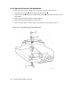
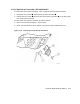
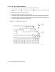
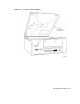
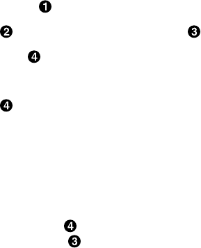
To remove tension sensor/roller guide 2, refer to Figure 5–36 and proceed as follows:
1. Disconnect connector J5 from the head circuit board.
2. Remove the screw attaching the roller guide , then remove the roller guide.
3. If there are any shims , save them.
NOTE
Any shims removed from the location of tension sensor/roller guide 2
must be used again when replacing the roller guide. Do not swap shims
between roller guides.
To replace tension sensor/roller guide 2, perform the removal procedure in reverse order and
adhere to the following note.
NOTE
If you saved any shims when you removed the roller guide, place them
between the roller guide and the mounting plate.
5–56 Removal/Replacement Procedures