
Technical data

6.2 Read Threshold Adjustment
The read threshold adjustment calibrates the read/write head by adjusting the write current to
the head and setting the read-after-write threshold for all densities. To make this adjustment,
proceed as follows:
1. Switch on the drive.
2. Load a reference level tape, or a known good tape, with a write-enable ring. Data will be
written to the tape.
3. Run Service Aid 513. It automatically adjusts the read threshold. For information on the
service aid, refer to Section 4.5.4.1.
6.3 Skew Adjustment
The skew adjustment sets the coils in the read/write head so that they align with recorded
data on a tape. This ensures that a tape written to in this drive may be read on another
drive. To perform this adjustment, proceed as follows:
1. Place the tape drive in the service access position (refer to Section 5.3).
2. Switch on the drive.
3. Load a master skew tape without a write-enable ring.
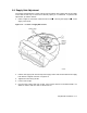
4. Connect an oscilloscope probe to pin 10/19 of connector J6 of the head circuit board.
Connect the ground clip to pin 20 of J6.
5. Set the controls of the oscilloscope as follows:
Gain—0.2 volts/division
Trigger—Internal, (+), ac
Sweeptime—2 microseconds/division. Adjust the time base so that one period of the
wave form fills the display.
6. Start Service Aid 222 in the Robot Mode (refer to Section 4.5.3.3).
CAUTION
To prevent the master skew tape from being damaged, reverse the tape
direction only at BOT and EOT, and do not use the REWIND switch to
move the tape.
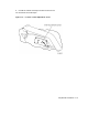
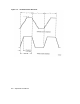
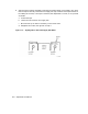
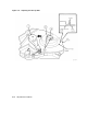
7. While running the tape forward and then in reverse, turn the skew adjustment screw
(see Figure 6–2) until the outputs of all tracks fall within 27 percent or less of the data
time as shown in Figure 6–3. (The screw can be reached through the circular hole in the
center of the head circuit board.)
8. Apply glyptol or torque seal to the skew adjustment screw. The Digital part number for
glyptol is 90-09536-00, however, any non-conductive sealant of this type may be used.
6–4 Adjustment Procedures