
Technical data
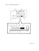
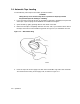
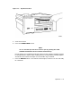
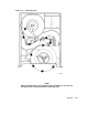

Table 2–1: TSZ07 Controls and Indicators
Item Function
AC Power Switch Located at the rear of the drive (not shown in Figure 2–1). When set to the on
(1) position, ac power is applied to the tape drive power supply. When set to off
(0), ac power is disconnected from the power supply. This switch must be on to
operate the drive.
CAUTION
Once the drive is installed and running on a host
system, setting the switch to off (0) may interrupt
the normal operation of the system.
When ac power is applied to the power supply, the drive initializes, causing the
following to occur:
1. Load Rewind, Unload, Online, Wrt En Test, and Density Select indicators
flash and TESTING appears on the display.
2. TESTING changes to TESTPASS and the indicators continue to flash.
3. Indicators extinguish.
4. Display goes blank, then the Unload and On/Off indicators light showing
that the tape drive is ready for loading tape operation.
Front Door When opened, provides access to the supply hub for the insertion or removal
of a reel of tape. Also provides access to the manual release switch. The front
door must be closed for operation.
Manual Release
Switch
When pressed, engages/retracts the supply hub pawls to enable the loading
/unloading of a reel of tape. Used when performing the procedure for manually
loading/unloading a reel of tape.
Load Rewind
Indicator
When flashing, indicates a tape is being loaded.
Unload
Indicator
When flashing, indicates that a tape is being unloaded. When lit, indicates that
a tape is unloaded. When not lit, indicates that there is no tape loaded in the
drive.
Online
Indicator
When lit, indicates the drive is on line. When extinguished, the drive is off
line.
Wrt En Test
Indicator
When lit, indicates that the loaded tape has a write-enable ring.
Density Select
Indicator
Flashes along with all other indicators during initialization, when the AC
Power Switch or ON/OFF Switch is set to on.
Alphanumeric
Display
Displays status and error messages during normal operation and while in the
service aid mode as described in Chapter 4.
On/Off
Indicator
When lit, indicates that dc power is applied to the drive circuits and that
the drive is ready to operate. When not lit, indicates that the dc power is
disconnected.
2–2 Operation