
Technical data
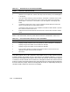
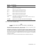
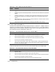
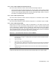


Table 4–11: Switch Functions in the Execution Mode
Switch Function in Execution Mode
1 Increments the next operation in the cycle.
2 Aborts the current operation, rewinds, and skips to the next density. SKIP DEN appears
in the display.
3 Locks and unlocks switching to the next density. The default is unlocked, which causes
switching. Locked causes continuous cycling in the current density until switch 3 is
pressed again or the service is terminated. LOCK DEN appears in the display when
locked.
4 If pressed once while service aid is running, enables the Status Mode and causes the
service to be exited after the Status Mode is exited.
If pressed once after the service aid is completed, it enables the Status Mode. If pressed
twice, the drive exits the service aid.
5 Enables the Status Mode and allows the service aid to continue after the status mode is
exited.
While in the Status Mode, the front panel switches function as described in Table 4–12.
Table 4–12: Front Panel Switch Functions in the Status Mode
Switch Function in Status Mode
1 Displays the total number of errors for all densities. TOTAL message is in the display.
2 Displays the type and number of errors detected in 1600 bpi.
3 Displays the type and number of errors detected in 6250 bpi.
4 Exits the Status Mode and re-enters the Execution Mode or exits the service aid,
depending on when the Status Mode is enabled.
5 No function.
Once either switch 1, 2,or3is pressed to select which errors to view, switch 1 must be
pressed to display the number of errors and retries in the following sequence. If no errors
occurred, the message NO ERRS appears when switch 1 is pressed. Once the above sequence
is entered, it cannot be exited until all of the error messages have been read, and the STATUS
prompt is reached. During the sequence only switch 1 functions to step through the sequence.
From the STATUS prompt, switches 1 through 4 then function as explained previously for
the Status Mode. Table 4–13 lists the error messages.
4–16 Troubleshooting