
Technical data
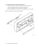
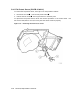
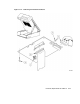

5.4.8 Front Panel Display Circuit Board (P/N 29-28468-01)
To remove the front panel display circuit board, see Figure 5–11 and proceed as follows:
1. Remove the front panel (refer to Section 5.4.7).
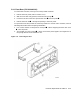
2. Release the front panel display circuit board from the four standoffs by placing a board
removal tool over the standoff and gently prying the board away from the standoff.
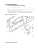
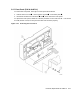
3. Connector J5, on the opposite side of the board, connects to the control switch circuit
board shown in Figure 5–5.
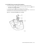
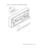
To replace the front panel display circuit board, follow the removal procedure in the reverse
order. Make sure that connector J5 on the front panel display board connects to the control
switch circuit board.
5–18 Removal/Replacement Procedures