
Technical data
5.4.9 Head Circuit Board (P/N 29-28478-01)
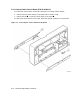
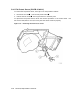
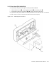
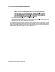
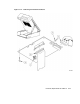
To remove the head circuit board, see Figure 5–12 and proceed as follows:
CAUTION
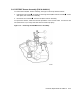
When removing or replacing the head circuit board, be careful not to
damage the head cables plugged into J3 and J4 of the head circuit board;
they are fragile. The cable plugged into J3 (closest to J2 ) is referred
to as the Read Head Flex Circuit Assembly (P/N 29-28473-01) in Table 5–1.
The cable plugged into J4 (next to J3 ) is referred to as the Write/Erase
Flex Circuit Assembly (P/N 29-28472-01) in Table 5–1.
1. Disconnect connectors J1 ,J2 , J3, J4 and J5 .
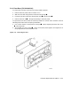
2. While supporting the head circuit board, remove the three screws attaching the board
to the top plate, then remove the board from the drive.
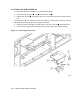
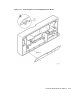
To replace the head circuit board, follow the removal procedure in the reverse order. When
connecting the head cables, the printed-circuit-board portion of each connector faces outward
and the ninety-degree pins face inward. After replacing the head circuit board, calibrate the
read/write head using Service Aid 513 (refer to Section 4.5.4.1).
5–20 Removal/Replacement Procedures