
Technical data
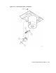

5.4.12 Interface Circuit Board (P/N 29-28477-01/29-30410-01)
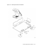
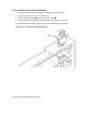
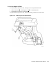
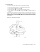
To remove the interface circuit board, see Figure 5–15 and proceed as follows:
1. If possible, record configuration parameters before replacing the board. Use Service Aid
142 to review the configuration parameters. For information on Service Aid 142, refer to
Section 4.5.2.6.
2. Remove the read/write formatter circuit board (refer to Section 5.4.19).
3. Disconnect connectors J1 ,J5 , and J6 .
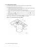
4. Release the interface circuit board from the six standoffs by placing the board removal
tool over each standoff and gently prying the board away from the standoff.
To replace the interface circuit board, proceed as follows:
1. Follow the removal procedure in the reverse order.
2. Run Service Aid 524 (refer to Section 4.5.4.2).
3. Run Service Aid 525 (refer to Section 4.5.4.3).
4. Run Service Aid 513 (refer to Section 4.5.4.1).
5. If the default configuration parameters need to be changed, run Service Aid 142 (refer to
Section 4.5.2.6).
6. Run Service Aid 543 (refer to Section 4.5.4.6).
7. Run Service Aid 542 (refer to Section 4.5.4.5).
5–26 Removal/Replacement Procedures