A Harman International Company S-DISC II™ PROCESSING RP-12 Guitar Signal Processor/ Foot Controller and Preamp Owner's Manual
RP-12 Owner’s Manual DECLARATION OF CONFORMITY Manufacturer’s Name: Digitech Manufacturer’s Address: 8760 S. Sandy Parkway Sandy, Utah 84070, USA declares that the product: Product Name: RP-12 Product Options: All (requires a Class II power adapter that conforms to the requirements of EN6005, EN60742, or equivalent).
RP-12 Owner’s Manual Table Of Contents . . . . . . . . Introduction . . . . . . . . . . . . . Safety Precautions . . . . . . . Lithium Battery Warning Warranty . . . . . . . . . . . . . . . . . . . . . . . . . . . . . . . . . . . . . . . . . . . . . . . . . . ...........1 ...........4 ...........4 ...........5 ...........6 Section 1 - Startup Supplying power . . . . . . . . . . . . . . . . . . . . . . . . . . . 7 Line Conditioning. . . . . . . . . . . . . . . . . . . . . . . . . . .
2 Section 5 - RP-12 Functions RP-12 Owner’s Manual Delay / Sampler. . . Delays . . . . . . Sampler . . . . . Pitch Shifters . . . . . Detuners. . . . . Whammy™. . . Arpeggiators . . Modulation Effects . Choruses . . . . Flangers . . . . . Phasers . . . . . Tremolos . . . . Auto Panners . Mixers . . . . . . . . . . More . . . . . . . . . . . Noise Gates . . DSP Level . . . Wahs . . . . . . . Duckers . . . . . Phase Inverter . . . . . . . . . . . . . . . . . . . . . . . . . . . . . . . . . . . . . . . .
RP-12 Owner’s Manual Section 8 - MIDI Setup About the MIDI Set-Up. . . . . MIDI Channel . . . . . . . . . . . Send Program . . . . . . . . . . . Program Send Map . . . . . . . Devices . . . . . . . . . . . . Device Map . . . . . . . . . Program Receive Map . . . . . Assign CC # to a Parameter Display CCs . . . . . . . . . . . . Bulk Dump . . . . . . . . . . . . . Program Dump . . . . . . . . . . MIDI merge . . . . . . . . . . . . . . . . . . . . . . . . . . . . . . . . . . . . . . . . . . . . . . . . .
4 Introduction RP-12 Owner’s Manual Congratulations, and thank you for purchasing the DigiTech RP-12 Guitar Signal Processor / Preamp. The RP-12 offers you a fresh approach to guitar sound creation, giving you the hottest tones and total control of the best digital effects in the industry. DigiTech’s revolutionary S-DISC II ™ processor makes it all happen.
RP-12 Owner’s Manual 5 These symbols warn that there are no user serviceable parts inside the unit. Do not open the unit. Do not attempt to service the unit yourself. Refer all servicing to qualified personnel. Opening the chassis for any reason will void the manufacturer’s warranty. Do not get the unit wet. If liquid is spilled on the unit, shut it off immediately and take it to a dealer for service. Disconnect the equipment during storms to prevent damage. U.K.
6 Warranty RP-12 Owner’s Manual 1. The warranty registration card must be mailed within ten days after purchase date to validate this warranty. 2. DigiTech warrants this product, when used solely within the U.S., to be free from defects in materials and workmanship under normal use and service. 3.
RP-12 Owner’s Manual 7 Section 1 - Startup Line Conditioning - The RP-12 is sensitive to voltage drops, spikes, and surges. Interference such as lightning or power “brownouts” can seriously, and in extreme cases, permanently damage the circuitry inside the unit. Here are some ways to avoid this type of damage: Supplying power • Spike/Surge Suppressors - This is an inexpensive solution to all but the severest of AC line conditions.
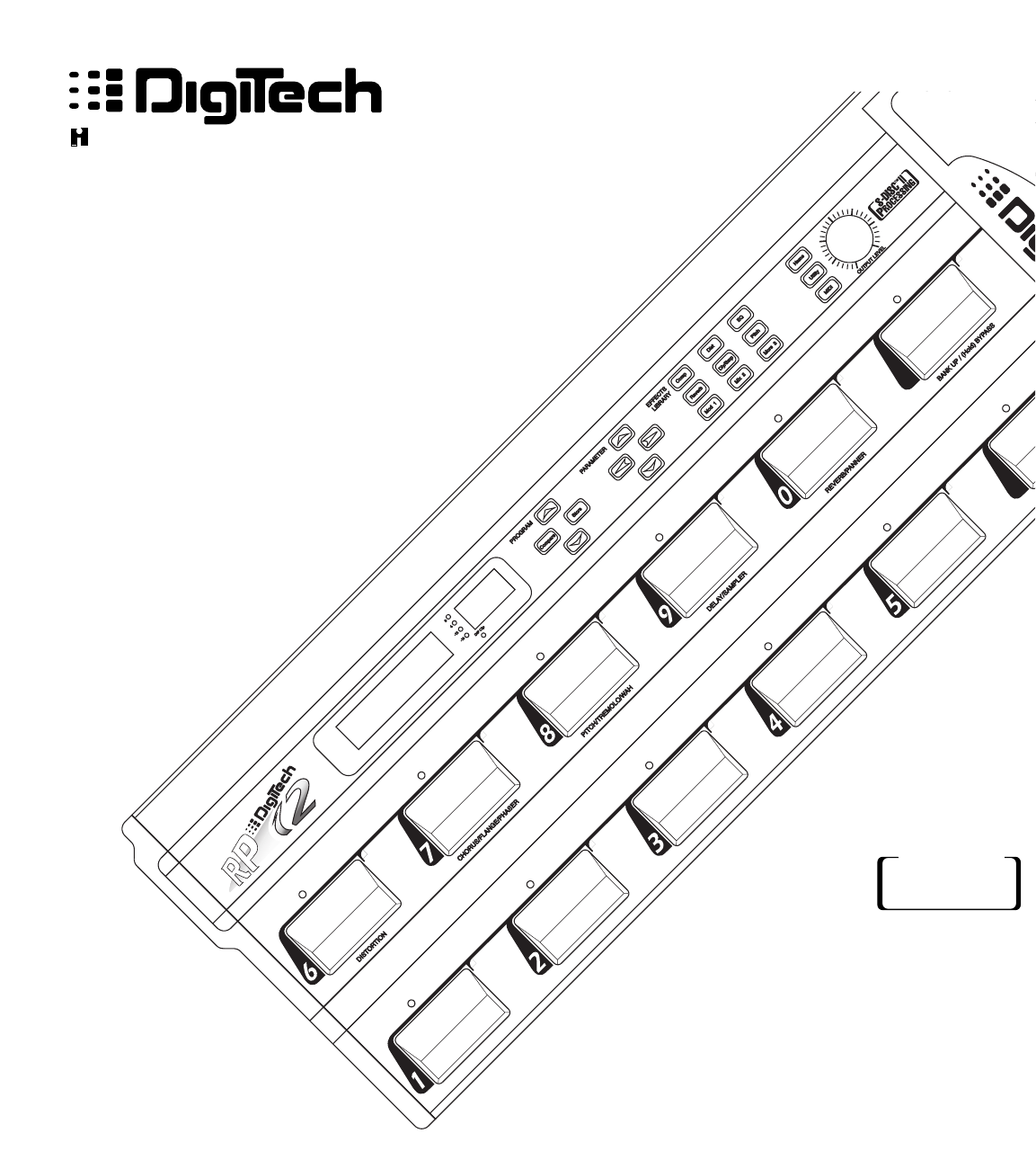
8 RP-12 Owner’s Manual 2) Display Window - The display window shows all current operating and programming information and is comprised of several parts: the LCD display, the input level meter, the Program number indicator, and DSP Clip indicator LEDs. The LCD display shows all Program names, Parameters and Parameter values, and is the communication interface between you and the RP-12. The input level meter monitors the level of the signal entering the digital section.
RP-12 Owner’s Manual 9 these functions include, Utility functions such as LCD contrast, Pedalboard , and MIDI setups (including transmit & receive maps). Buttons in this group are: , , and . 7) Main Output Level - This controls the overall output level of the RP-12. It also controls the overall level of the headphones. 8) Continuous Control Pedal - This volume-type pedal allows realtime control over Parameters in the RP-12.
10 MIDI and Audio Setups RP-12 Owner’s Manual The following diagrams show possible MIDI and audio routing setups for the RP-12.
RP-12 Owner’s Manual 11 Input Left Out Right Out To Multitrack and/or Studio Monitors Mixer Inputs Recording Setup (Use Cabinet Emulator) Input MIDI Out Left Out Right Out MIDID In MIDI Keyboard, Sequencer, or Computer o Amplifier(s) Using external MIDI control Section 1 - Startup
RP-12 Owner’s Manual 12 Section 2 - Basic Operations Program Architecture The Program’s Parameter architecture in the RP-12 has been designed to be a linear series of items, rather than a multiple-level menu (see diagram). In other words, instead of including several submenus under a single Parameter heading, all Parameters are included in a single level, and are accessed using the and Parameter keys.
RP-12 Owner’s Manual 13 • To scroll at high speed through the Programs in memory, press and hold either the or Program key. 2) The second method uses the RP-12’s pedalboard. When you change programs using the pedalboard, any unstored modifications you have made to a Program will be lost. 3) The third method is through the use of MIDI. This method will be covered later in the MIDI section of this manual, pg. 58.
14 RP-12 Owner’s Manual CHANGING THE TUNING REF You can easily change the RP-12’s tuning reference by using the Parameter buttons while in tuner mode. The top line of the display will show the current setting. The default factory setting is: A=440 Hz. The tuning reference control ranges from 427 Hz to 453 Hz, which is the equivalent of ±50 cents (1/2 semitone) in either direction from 440 Hz. Scrolling down below 427 Hz, you can access the alternative tuning references of: A= G#, A=G, and A=F#.
RP-12 Owner’s Manual 15 On/Bypass parameter, by either pressing the Parameter button five times, or pressing the Effects Library Button.
16 RP-12 Owner’s Manual Section 3 - Programming Using the Function buttons The RP-12 has three Function keys. They are located in the bottom row of the Effects Access buttons and they share buttons with the , , and options. Each Function key is numbered and performs several functions in the Utility and MIDI modes (depending on the selected menu screen). These buttons are also used in the Program naming process (see Storing/Naming on page 19). See pg. 49 for more on the Utility Button.
RP-12 Owner’s Manual 17 The Effects Library Buttons The Effects Library buttons are used to jump to specific places in a Program. For example, if a Program contains two choruses and you want to change the delay time on only one of them, you could press the Effects Library button from Program Title screen and you would jump to the first Parameter of the first chorus in the Algorithm. Press the button again, and you are taken to the first Parameter of the next chorus in the Algorithm.
18 RP-12 Owner’s Manual rus speed. Using this Program as an example for Program modification, the procedure for changing the Chorus Speed is as follows: • From the Program title screen, scroll to Program 2 using the Program buttons. The display reads: Clean and Tight DCho≥2TDly≥2Pans • Using the and Parameter buttons, scroll to the CHORUS SPEED Parameter. The display reads: Chorus Speed (0.
RP-12 Owner’s Manual you want and begin editing Parameters from there. 19 The Algorithm selection screen works in conjunction with the LED display to show the currently selected Algorithm number. When in the Algorithm selection screen, the LCD display looks something like this: ALGORITHM NAME--> Wham≥2TDly≥Revrb Comp Dist MVol≥ <-- EFFECTS ROUTING WITHIN ALGORITHM To select an Algorithm for a Program, the procedure is as follows: • From the title screen, press the Parameter key once.
20 RP-12 Owner’s Manual key puts a space into the Program name, and jumps you to the special characters in the character set. The key inserts an ‘0’, and jumps you to the numbers section of the character set. The complete procedure for naming and storing a Program is as follows: • After you have made all the necessary modifications to the Algorithm, press the button once. The RP-12 is now in Name mode.
RP-12 Owner’s Manual 21 • When the Program name appears as you want it, press the button to exit the name selection mode. Storing Programs Once you have dialed in the program how you want it and given it a name, press the button. The display reads: Store To Prg ## [PROGRAM NAME] This screen allows you to select the Program location in which you want to store the new Program.
RP-12 Owner’s Manual 22 SECTION 4 - EFFECTS AND PARAMETERS About the Effects Library The Effects Library consists of all the effects Modules you can find in the RP-12. Broken down into individual categories, specific Modules and their abbreviated library names are as follows: Analog Effects Module Name Compressor Distortion Module Abbrv.
RP-12 Owner’s Manual 23 Program. Options are: OVERDRIVE - Solidstate overdrive with extra punch. HEAVY SUSTAIN - Smooth, warm distortion sound with lots of sustain. GRUNGE- High gain distortion which is tight and highly focused for powerful rhythms and leads. Distortion Gain ..............Controls the amount of distortion produced by the RP-12. High settings produce greater gain and drive for effortless soloing, while low settings offer better nuance and touch control. Ranges from 0 to 11.0.
24 RP-12 Owner’s Manual DigiTech Audio Precision STD AMPL (dBr) vs FREQ (Hz) 20.000 15.000 10.000 Q= 5.0000 2 Q= 4 Q 0.0 = 8 -5.000 -10.00 -15.00 -20.00 100 1k 10k With a Q setting of 2, you can see that a large number of frequencies are affected by boosting the center frequency. Now take a look at the middle and lower curves in the diagram, and notice the much narrower bandwidth of the curves with a Q setting of 4 and 8.
RP-12 Owner’s Manual Reverbs Module Name BigVerb MFX Reverb Gated Reverb Big Verb/MFX Reverb Module Abbrv. Big MVerb GtRvb Description Studio-quality reverb. Appears in multi-effects Algorithms. Professional gated reverb 25 Bigverb is the flagship reverb Module of the RP-12. It contains 14 Parameters, giving exceptional soundfield and tonal shaping control over reverberation. Bigverb is capable of producing reverberation of virtually any size, shape, depth, timbre or soundfield location.
INITIAL SOUND AMPLITUDE 26 RP-12 Owner’s Manual EARLY REFLECTIONS SUBSEQUENT REVERBERATIONS TIME EARLY RFLCT PREDELAY RV PRE-DELAY RV SIZE The BigVerb’s ER Spread, ER Shape and ER DIFFUSION controls let you modify the build/decay of the early portion of the reverberation envelope and the relative reverberation time of the midrange reverb frequencies. The ER Shape Parameter controls the shape of the early reflection envelope.
RP-12 Owner’s Manual 27 higher settings spread the same number of reflections out over a longer period of time. Ranges from 25 to 300 milliseconds. (ER settings in BigVerb only). ER Shape ......................Controls the shape of the early reflection envelope. There are 10 different early reflection envelope shapes. The following diagram shows all the available early reflection envelope shapes.
28 RP-12 Owner’s Manual RV Spread.....................Controls the dispersal and density of reverberations through the course of the early portion of RV RT60. BigVerb’s RV Spread varies in 20 ms increments from 20-180 ms. MFX Reverb’s RV Spread varies in 10 ms increments from 10-100 ms. RV Diffusion ..................RV Diffusion controls the smoothness of the reverberation. In a real room, reverberation is naturally diffused by air.
RP-12 Owner’s Manual 29 Gated reverbs usually include adjustable thresholds to set the point at which the reverberations will be gated (cut off). The RP-12’s RV DECAY TIME control behaves in a similar way, except that instead of setting the length by level (threshold), the length is set by time (in milliseconds). In the left side of the diagram that follows, you can see that reverberations occurring after RVB GATE TIME are muted. This causes the reverb to cut off abruptly.
30 RP-12 Owner’s Manual found in the library, and their Parameters are as follows: Gated Reverb On / Off ..Turns the Module on or off. Reverb Pre-Delay..........Sets the amount of time before the reverberations are heard. Adjustable from 0 to 100 milliseconds. Rvb Decay Time............Controls the amount of time before the gate cuts off the reverberations. Variable from 20 to 1000 milliseconds. Rvb Envelope ................
RP-12 Owner’s Manual Delays/Sampler Module Name Mono Delay x.x 2Tap Delay x.x 4Tap Delay x.x Stereo Delay Modulated Delay Sampler Delays Module Abbrv. Dly x.x 2TDly x.x 4TDly x.x SDly ModDly Smpl1.5 Description 1-tap digital delay 2-tap digital delay 4-tap digital delay Stereo digital delay Digital delay with pitch modulation 1.5 second sampler 31 All the delays in this group have the same basic Parameters for controlling the behavior of the Module.
RP-12 Owner’s Manual 32 the hundred milliseconds position (one place to the right of the decimal), you will increase the delay time in increments of 100 milliseconds. Pressing the Parameter button moves the cursor to the third position to the right of the decimal point, or milliseconds position. Each press of the Parameter button from this position increases the delay time in single millisecond steps.
RP-12 Owner’s Manual 33 out of the turnaround points. TRIANGLE is a linear modulation effect, and ramps the pitch of the wave up and down with no slowing at turnaround points. LOGARITHMIC and EXPONENTIAL waveforms are more dramatic in their effect on the signal, producing a type of bouncy oscillation. This Parameter appears only in Modulated Delays. Sampler The RP-12 offers a studio-grade sampler Module for maximum flexibility and usefulness. It uses a 40 kHz sample rate for increased sound quality.
34 RP-12 Owner’s Manual al triggering is active. There are two audio triggering options and one manual triggering option. They behave as follows: when set to MANUAL TRIG, samples and sampling are triggered using manual methods (pedalboard, front panel, etc.). When set to AUDIO TRG ONCE, the sample is triggered once using an audio source of a set level (determined by the setting of INPUT TRIG LEVEL), following which, this Parameter is automatically reset to MANUAL.
RP-12 Owner’s Manual Pitch Shifters Module Name Pitch Shift Smooth Pitch Harmony Mono Detune Dual Detune Module Abbrv.
36 RP-12 Owner’s Manual Pitch Level.....................Controls the overall level of the pitch shift. Variable from 0 to 100. Pitch Shft Amount .........Sets the interval between the original note and the pitch shifted note. Variable from -24 to +24 (4 octaves). Key (Harmony Only)......Allows you to set the musical key for harmonies. If the song you are playing is in G Major, you select G for the scale. Scale (Harmony Only)...Selects the scale type for the harmony you want to hear.
RP-12 Owner’s Manual the detuned note is heard. 37 NOTE: The dual detuner has a predelay for each detune voice. Detune Amount .............Controls the amount of detuning. Variable, in cents, from -100 to +100. Whammy™ Whammy On / Off .........Turns the Module on or off. When Modules are turned off, their Parameters disappear from the Parameter menu. To see the Parameters, you must turn the Module on. Whammy Function ........Selects the function of the Whammy Module.
RP-12 Owner’s Manual 38 Arpeggio Detune ...........Determines the amount of detuning applied to the shifted note. Variable, in cents, from -100 to +100. Arp Pch Tracking...........Controls the sound quality/tracking speed of the pitch shifted material. This control should be set in relation to the amount of pitch shifting to be performed. That is, as the pitch shift interval increases, ARP PCH TRACKING should be increased to optimize sound quality. Ranges vary from 0-100 cents to 12-24 tones.
RP-12 Owner’s Manual 39 forms set 90 degrees out of phase. Chorus Parameters are as follows: Chorus On / Off .............Turns the Module on or off. When Modules are turned off, their Parameters disappear from the Parameter menu. To see the Parameters, you must turn the Module on. Chorus Level .................Controls the overall level of the chorus. Variable from 0 to 100. Chorus Speed ...............Controls the speed of the chorus sweep. Variable from 0.06 to 16.00 Hz. Chorus Depth ................
40 RP-12 Owner’s Manual Flange Level..................Controls the overall level of the flange. Variable from 0 to 100. Flange Delay .................Sets the amount of delay present in the flange effect. Varies from 0 to 60.00 milliseconds. Flange Feedback ..........Controls the amount of flanged sound fed back to the input of the Module. High regeneration settings produce dramatic and interesting unnatural sounds. Varies from -99% to +99%. This Parameter can also be turned off. Flange Speed ............
RP-12 Owner’s Manual 41 new life into this classic effect, providing totally transparent volume modulation of sound sources. Tremolo On / Bypass ...Turns the Module on or off. When Modules are turned off, their Parameters disappear from the Parameter menu. To see the Parameters, you must turn the Module on. Tremolo Level ...............Controls the output level of the tremolo effect. Tremolo Speed..............Controls the tremolo speed (speed of modulation). Variable from 0.00 to 16.00 Hz.
42 RP-12 Owner’s Manual The RP-12’s Mixer modules enable the use of effects in parallel configurations. They allow multiple Module outputs to be connected to a single input of another Module. Each mixer channel is equipped with an input level to give you maximum control over levels coming from and going to different Modules. Mixer Modules appear in 1-out, 2-out, and 3-out configurations. 2-out and 3-out configurations include pan controls on the inputs.
RP-12 Owner’s Manual quietest status. The Parameters are as follows: 43 Effect On / Bypass ........Turns the Module on or off. When Modules are turned off, their Parameters disappear from the Parameter menu. To see the Parameters, you must turn the Module on. NG Threshold ................Sets the level at which the gate will open. Ranges from -∞ to +∞. NG Hold Time ...............Controls the amount of time the signal must remain below the off-threshold before NG RELEASE TIME begins.
44 Duckers RP-12 Owner’s Manual Level..............................Controls the overall level of the wah effect. Varies from 0 to 100. Wah Pedal Position.......The PEDAL POSITION Parameter reflects the current setting of the continuous control device used to control the wah effect. This Parameter can be modified using the RP-12’s pedal to perform the wah function. As the Parameter is modified, the tone of the original note will change. Varies from 0 to 127.
RP-12 Owner’s Manual 45 Phase Inv Level.............Set the level of the output signal from the Phase Inverter Module. Adjustable from 0 to 100.
RP-12 Owner’s Manual 46 Section 5 - RP-12 Functions The RP-12 has two basic types of functions: Pedalboard functions and MIDI functions. Internal Functions The Pedalboard functions can be broken down into two sections: Pedalboard functions that affect the processor directly and Pedalboard functions that interact with MIDI and then affect the processor.
RP-12 Owner’s Manual 47 The Pedalboard functions that affect the processor directly include: Program changes, Program Up/Down, List Up/Down, Bank Up/Down/Tuning, and Bypass. The Pedalboard functions that interact with MIDI and then affect the processor include: Toggle CC and CC Pedal. The CC Pedal channel and Toggle CC channel allow MIDI CC information to be sent out the MIDI port allowing for control of the RP12, external units, or both together.
48 RP-12 Owner’s Manual While performing, the CC Pedal= command can be used to assign a different Continuous Controller number to the CC Pedal (defaulted to CC 4 at the factory). Upon hitting the assigned pedal, the CC pedal will be reassigned from its current controller, number to the new continuous controller number. Hitting the footsitch again will assign the pedal back to the default CC number. Changing the Program will always cause the pedal to be assigned to the default CC number.
RP-12 Owner’s Manual Section 6 - Pedalboard set-up 49 The Utility section of the RP-12 contains the pedalboard setup menu. This menu is reached by pressing the button. The procedure is as follows: • Press the button once. The display reads: ¡Pedalboard ™Contrast 5 ≥ This is the main Utility options menu. From this selection screen, you are able to choose the option you want using the ¡,™,&£ Function buttons.
50 Pedals RP-12 Owner’s Manual The ¡Pedals option allows different functions to be assigned to each of the pedals on the pedalboard. • From Program mode, press the button once. • Press the Function button once. The display reads: ¡Pedals ™CC Ped £PrgList Assign≥ •Press Function button again. The display reads: ¡Bank 1 ™Pedal 1 £[assignment] 1 There are 25 Banks available, each with 10 pedal assignments.
RP-12 Owner’s Manual CC Pedal 51 This section allows you to assign the CC Pedal’s CC number and transmit Channel number. • From Program mode, press the button once. • Press the Function button once. The display reads: ¡Pedals ™CC Ped £PrgList Assign≥ Assign CC Pedal • Press Function button . The display reads: ¡Assign CC Pedal ™Calibrate Pedal •Press Function button .
RP-12 Owner’s Manual 52 ¡Assign CC Pedal ™Calibrate Pedal • Press Function button . The display reads: Set Pedal Down (Forward) press¡ • Move the pedal to its full forward (toe down) position, and press Function button . The display reads: Set Pedal Up (Back), press ™ • Move the pedal to its full back (toe up) position, and press Function button . When the display returns to the Utility setup menu, you have successfully calibrated the CC pedal.
RP-12 Owner’s Manual 53 buttons, you will scroll through the number of steps that you assigned from the above List Size. For example: if you assigned your List Size to be 6 steps, you will have 6 assignments available. You may have noticed, as you increment and decrement the Step Number, the Program Name and number change with the step number. If you want to change the Program number assigned to the step, Press Function button . The cursor should move under the Program number.
54 RP-12 Owner’s Manual ¡LEDs:Normal ≤™Bank Names • Press Function button and the display will look something ¡BANK NUMBER 1 Top 5-1 • Press Function button button and the display will look something like this: Top 5-1 ¡CAPs ™SPC £NUM • Using the Parameter buttons, scroll to the character you want to use, or press one of the Function buttons. When you have selected the character you want, press the Parameter key.
RP-12 Owner’s Manual 55 Section 7 - RP-12 set-up The Utility section of the RP-12 contains the Contrast Menu, Output Mode, Cabinet Emulation Menu, Sales Banner Menu, and the Reinitializing Menu. These menus are reached by pressing the button. The procedure is as follows: • (Step 1) Press the button once. The display read: ¡Pedalboard ™Contrast 5 ≥ This is the main Utility options menu.
56 Cabinet Emulator RP-12 Owner’s Manual The ™CabEm: option allows you to select: All On , All Off, and Local. All On indicates the Cabinet Emulation Parameter will always be set to on. All Off indicates the Cabinet Emulation Parameter is always off. Local indicates the stored Parameter value is being used. From the Program title screen, press the button. The display reads: ¡Pedalboard ™Contrast 5 ≥ • Press the Parameter button.
RP-12 Owner’s Manual Reinitializing the RP-12 57 Reinitializing the RP-12, restores the factory presets and deletes any user presets stored or not stored. It will be exactly as it was the day it left the factory new. From the Program title screen, press the button. The display reads: ¡Pedalboard ™Contrast 5 ≥ • Press the Parameter button, twice. The display reads: ¡Sales:Off ≤™Reinitialize •Press Function button .
58 RP-12 Owner’s Manual SECTION 8 - MIDI set-up The RP-12’s MIDI set-up allows you to access and change MIDI Parameters. This is where you are able to edit your MIDI channels, turn the Program send on or off, edit the Program send and receive maps, edit the Device number, assign CC numbers, dump MIDI SysEx data, and turn MIDI merging on or off. These menus are reached by pressing the button. The Procedure is as follows: • (Step 1) Press the button once.
RP-12 Owner’s Manual Program Send Map 59 Device mapping allows the RP-12 to act as a controller for up to four other devices. From the MIDI options menu: • Press the Parameter button. The display reads: ¡Prg Send Map ≤™Prg Rcv Map ≥ • Press Function button . The display reads: ¡Device 1 ™MIDI Ch:1 ≥ The cursor is now under the Device number on the above screen. At this point, each time you press Function button , you should increment through the four Device numbers.
60 Program Rcv Map RP-12 Owner’s Manual the RP-12. If this Parameter is set to DISABL, the selected RP-12 Program Change will send nothing to the external device. Select the Program Change number that will be sent (1-128, DISABL) using the Parameter buttons. The Program Recieve Map function allows you to map incoming MIDI Program Changes to any Program in the RP-12. From the MIDI options menu (step 1): • Press the Parameter button.
RP-12 Owner’s Manual 61 • From the Parameter screen press and hold the button. The display reads something like: ¡Link # = Nolink ™Assign NOTE: All presets have factory established CC Links. If the selected Parameter is not linked, it will select the next available CC link for assignment. • Press Function button once.
62 RP-12 Owner’s Manual NOTE: The MINIMUM CC VALUE and MAXIMUM CC VALUE Parameters allow you to limit the range of the continuous controllers in the full on and full off positions. The values you select on these two screens determine the behavior of the continuous controller. For example, if a Parameter ranges from 0-100 and MINIMUM CC VALUE is set at 40, the lowest the Parameter can go to via continuous control is 40. Likewise, if MAXIMUM CC VALUE is set at 90, the CC range would run from 40 to 90.
RP-12 Owner’s Manual ¡Link # = CC# ™New£[PARAM NAME] 63 This screen gives you the option of either reassigning the link (NEW) or selecting a different Local CC Link number. To reassign the link: • Press Function button . If a Parameter has not been selected for continuous control, the display briefly reads: Move to Param to Link Local CC after which you are returned to the Program to select a Parameter for continuous control.
64 Bulk Dump RP-12 Owner’s Manual This option allows you to dump a SysEx copy of the entire contents of the RP-12 memory out the MIDI port. This is particularly useful for backing up the memory of the RP-12, or copying all the Programs from one RP-12 to another. From the MIDI options menu (step 1): • Press the Parameter button, three times. The display reads: ¡Bulk Dump ≤™Program Dump ≥ • Press Function button once.
RP-12 Owner’s Manual 65 Dump ¡Prg:### ™as:### £Start • Using the and Parameter buttons, select the Program number you want to dump out the MIDI port. • Press Function button once. Note that the cursor moves • Using the Parameter buttons, select the Program number location in which you want the dumped Program to appear. To abort the operation press the button.
66 RP-12 Owner’s Manual Section 9 - appendix Specifications A/D Converter: 16 bit PCM D/A Converter: 16 bit PCM Sampling Frequency: 40 kHz DSP Section: Architecture: Static-Dynamic Instruction Set Computer (S-DISC II™) Digital Signal Path Width: 24 bits (144.5 dB) Internal Data Path Width: 48 bits (289 dB) Dynamic Delay Memory: 64k x 24 bits (1.68 seconds) Static Delay Memory: 256 24-bit registers (6.55 milliseconds) Data ALU Processing: 10.0 MIPS Address ALU Processing: 15.
RP-12 Owner’s Manual 67 Factory Algorithm Diagrams Following, are block diagrams of all the Factory Algorithms. These diagrams show all of the input and output information associated with each Module, as well as the signal path routings for each of the 36 Algorithms.
RP-12 Owner’s Manual 68 Algorithm #6 DCho -> 2TDly -> 2 Pans INPUT Inp 1 DCho Dual Chorus 3x1 Mono 3 x 1 Mixer Cho 1 Cho 2 Out 1 Out 2 Inp 1 Inp 2 Inp 3 Out 1 Inp 1 2TDly 2-Tap Delay 1.
RP-12 Owner’s Manual 69 Algorithm #10 Wah -> Wham -> Cho -> Dly TWah Traditional Wah INPUT Inp 1 Wham Whammy Out 1 Inp 1 Out 1 Inp 1 DCho Dual Chorus Cho 1 Cho 2 3x2 Stereo 3 x 2 Mixer Out 1 Inp 1 In 1 Out L Out 2 Inp 2 In 2 Out R Inp 3 In 3 SDly Stereo Dly 5 Out 1 Out 2 4x2 Stereo 4 x 2 Mixer Out 1 Inp 1 In 1 Out L Out 2 Inp 2 In 2 Out R Inp 3 In 3 Inp 4 In 4 Inp 1 Inp 2 Out 1 Out 2 LEFT MAIN RIGHT MAIN Algorithm #11 Arpeggio2 -> Dly INPUT Inp 1 Inp 1 Arp A Arpeggiator 3x3 3 x 3 Mixer Out
RP-12 Owner’s Manual 70 Algorithm #14 Mod Dly -> Revrb MDly Modulation Delay INPUT Inp 1 2x3 2 x 3 Mixer Out 1 Inp 1 In 1 Inp 2 In 2 Out 1 Out 2 Out 3 Out 1 Out 2 Out 3 Inp 1 4x2 Stereo 4 x 2 Mixer MVRB MFX Reverb Out 1 Inp 1 In 1 Out 2 Inp 2 In 2 Inp 3 In 3 Inp 4 In 4 Out L Out R Out 1 Out 2 LEFT MAIN RIGHT MAIN Algorithm #15 Wham -> 2TDly -> Revrb Wham Whammy INPUT Inp 1 Out 1 Inp 1 3x1 Mono 3 x 1 Mixer 2TDly 2 Tap Delay 8 Tap 1 Tap 2 Out 1 Out 2 Inp 1 Inp 2 Inp 3 Out 1 Inp 1 5x2 Ste
RP-12 Owner’s Manual 71 Algorithm #18 DCho -> 4TDly -> Pan 5x1 Mono 5 x 1 Mixer Inp 1 Inp 2 Inp 3 Inp 4 Inp 5 INPUT Inp 1 DCho Dual Chorus 3x3 3 x 3 Mixer Cho 1 Cho 2 Out 1 Inp 1 In 1 Out 2 Inp 2 In 2 Inp 3 In 3 Out 1 Out 2 Out 3 Out 1 Out 2 Out 3 Inp 1 4TDly 4-Tap Delay 1.
RP-12 Owner’s Manual 72 Algorithm #20 DFla -> 4TDly -> Pan 5x1 Mono 5 x 1 Mixer Inp 1 Inp 2 Inp 3 Inp 4 Inp 5 INPUT Inp 1 DFla Dual Flange 3x3 3 x 3 Mixer Out 1 Inp 1 In 1 Out 2 Inp 2 In 2 Inp 3 In 3 Out 1 Out 2 Out 3 Out 1 Out 2 Out 3 Inp 1 4TDly 4-Tap Delay 1.
RP-12 Owner’s Manual 73 Algorithm #22 Gated Reverb LEFT INPUT Inp 1 GtRvb Gated Reverb 3x2 Stereo 3 x 2 Mixer Left Right Out 1 Inp 1 In 1 Out 2 Inp 2 In 2 Inp 3 In 3 Out L Out R Out 1 Out 2 LEFT MAIN RIGHT MAIN Algorithm #23 4PCho -> 2TDly -> SDuc INPUT Inp 1 4PCho 4-Phase Chorus Cho 1 Cho 2 Cho 3 Cho 4 5x3 5 x 3 Mixer Out 1 Out 2 Out 3 Out 4 Inp 1 Inp 2 Inp 3 Inp 4 Inp 5 In 1 In 2 In 3 In 4 In 5 Out 1 Out 2 Out 1 Out 2 Out 3 Inp 1 Out 1 Out 2 Out 3 Inp 1 Out 1 Out 2 Out 3 Inp 1 Ou
RP-12 Owner’s Manual 74 Algorithm #28 Dly -> Dual Chorus Dly Mono Delay 1.0 INPUT Inp 1 2x1 Mono 2 x 1 Mixer Out 1 Inp 1 Inp 2 Out 1 Inp 1 DCho Dual Chorus 4x2 Stereo 4 x 2 Mixer Cho 1 Cho 2 Out 1 Inp 1 In 1 Out 2 Inp 2 In 2 Inp 3 In 3 Inp 4 In 4 Out L Out R Out 1 Out 2 LEFT MAIN RIGHT MAIN Algorithm #29 Dly -> Dual Detune Dly Mono Delay 1.
RP-12 Owner’s Manual 75 5x1 Mono 5 x 1 Mixer Algorithm #32 Pitch -> 4TDly -> Pan LEFT INPUT Inp 1 Pch Mono Pitch Shift Inp 1 Inp 2 Inp 3 Inp 4 Inp 5 2x1 Mono 2 x 1 Mixer Out 1 Inp 1 Inp 2 Out 1 Inp 1 4TDly 4-Tap Delay 1.
RP-12 Owner’s Manual 76 Algorithm #34 Pch2 -> Dly INPUT Inp 1 Pch2 Smooth Pitch 2x1 Mono 2 x 1 Mixer Out 1 Inp 1 Inp 2 Out 1 Inp 1 2x1 Mono 2 x 1 Mixer Dly Mono Delay 1.0 Out 1 Inp 1 Out 2 Inp 2 Out 1 Out 2 LEFT MAIN RIGHT MAIN Algorithm #35 Whm2-> Dly INPUT Inp 1 Whm2 Smooth Whammy 2x1 Mono 2 x 1 Mixer Out 1 Inp 1 Inp 2 Dly Mono Delay 1.
Input A/D Converter D/A Converter Distortion Output Level Headphone Output 1/4" Output Left 1/4" Output Right Block Diagram S-DISC™ Processor (DSP) Compressor Meter RP-12 Owner’s Manual The following is a simplified block diagram of the RP-12.
78 RP-12 Owner’s Manual MIDI Implementation Chart Function...
RP-12 Owner’s Manual Preset List # Title Bank 1 Top Five-1 1 2 3 4 5 Shooting Star Clean and Tight Smart 3rds in A Dynamic Solo Wham and Eggs Bank 2 Top Five-2 6 7 8 10 Auto Wahtch It ! Post Hippie Hot Rod String Pad Bank 3 Alternative-1 11 12 13 14 15 Tune Me Down Dogs Day Nosey Meat Eaters Slapback Chorus Bank 4 Alternative-2 16 17 18 19 20 ..
80 RP-12 Owner’s Manual 80 Lively Strum 25 # Title Alg# Bank 17 Jazz/Fusion-1 81 82 83 84 85 Big Chorus Room Pedal Synth New Ages Fused 4ths Jazzman Chorus Bank 18 Jazz/Fusion-2 86 87 88 89 90 Fusion Tone Classic Jazz Take the 5th PedalSynth Lead Delay > Detune Bank 19 Studio-1 91 92 93 94 95 Melodic Solo Studio Clean Rhythmic Delays Duc My Echo 1.
RP-12 Owner’s Manual 81 Harmony Interval Charts Interval Major Minor Harm.Minor Mel.Minor Dorian Mixolydian Lydian üOct ü7th ü6th C C C C C C C B Bb B B Ab Bb B Ab Bb A A A A A üOct üOct üOct üOct Ref ¨2nd G G G G G G G F F F F F F F# E Eb Eb Eb Eb E E D D D D D D D C C C C C C C B Bb B B Bb Bb B ¨3rd A Ab Ab A A A A ¨4th ¨5th ¨6th ¨7th G G G G G G G ¨Oct Int. Lydian Aug.
8760 South Sandy Parkway Sandy, Utah, 84070 Telephone (801) 566-8800 FAX (801) 566-7005 International Distribution: 3 Overlook Dr Unit 4 Amherst, New Hampshire 03031 U.S.A. FAX (603) 672-4246 DigiTech™, S-DISC™, Whammy™ and Silencer™ are registered trademarks of Harman Music Group Incorporated Copyright © 1996 Harman Music Group Incorporated Printed In USA 9/96 Manufactured in the U.S.A. RP-12 18-2173-A OS v1.