
1A N-HO Scale Wired Mobile Decoder - Manual


© 2014 Digitrax, Inc. www.digitrax.com— 2 —
Parts List
1 DN136D Mobile Decoder
1 Instruction Sheet
1 DNWH Digitrax Easy Connect 8 Pin Harness
Installation Information
See the Digitrax Decoder Manual for complete decoder test procedures, instal-
lation instructions, programming and technical information. Digitrax manuals
and instructions are updated periodically. Please visit www.digitrax.com for the
latest versions, technical updates and additional locomotive-specic installation
instructions. CAUTION: Programming and layout track must not exceed
16V when using this decoder.
Installation Instructions
1. Carefully remove the locomotive shell from the frame following the
manufacturer’s instructions. Notice the orientation of the shell to the frame
so that you can reinstall correctly.
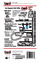
2. The DN136D uses the DNWH Digitrax Easy Connect 8 Pin Harness System
which consists of an approximately 4.5” harness that has a Digitrax 8 Pin
plug on one end and wires on the other. The harness allows the decoder to
be easily installed in a variety of locomotives. The ends of the wires of the
harness are wired to the motor connections, power pickup connections and
the lights as shown in Figure 1 below.
3. Plug the 8 Pin plug on the DNWH harness into the socket on the decoder
The plug is notched to t easily into the socket in only one orientation.
4. Replace the loco shell. You are now ready to run your locomotive. The
DN136D is factory programmed to address 03. You can easily customize the
address and other features. See section “Customizing Your Decoder” that
follows.
Figure 1: DN136D Wiring
Diagram
Warning: to prevent decoder
damage, be sure the motor
brushes are properly isolated
before applying power.
DN136D
Decoder