C omplete T rain C ontrol Mobile & Sound Decoder Manual Second Edition Includes: Digitrax Series 3, 4, 5 & 6 Mobile, Sound & Function Decoders L R et ocoN Digitrax, Inc. 2443 Transmitter Road Panama City, Florida 32404 www.digitrax.com Digitrax Manuals & Instructions are updated periodically. Please visit www.digitrax.com For the latest version of all manuals & instructions.
R Digitrax Mobile & Sound Decoder Manual Second Edition Table of Contents 1.0 Introduction..............................................................6 2.0 Digitrax Mobile and Sound Decoder Overview ....6 2.1 Digitrax Decoder Part Numbering System..........................7 3.0 Decoder Installation.................................................9 3.1 Decoder Installation Basic Steps.........................................9 3.2 Choosing a Locomotive......................................................
5.0 Decoder Programming.......................................... 28 5.1 5.2 5.3 5.4 5.5 What are Configuration Variables (CVs)?..........................28 Service Mode and Ops Mode Programming Methods......28 Programming Modes............................................................28 DCC Outputs: Programming & Layout Operation............29 Reading & Writing CVs........................................................29 6.0 CVs-Configuration Variables ............................... 30 7.
9.3.6 Rule 17 Dimming on F0Fwd and F0Rev......................56 9.3.7 Rule 17 AND Forward Ditch Lights.............................57 9.3.8 Alternating Double Pulse Strobes on F1 & F2...........57 9.4 Tables for Determining FX3 CV Values..............................58 9.5 FX3 Rate & Keep Alive Brightness CV62...........................59 9.6 Ditch Light Hold Over Time CV63.......................................60 9.7 Troubleshooting FX effects.................................................61 9.
Digitrax products incorporate material covered by multiple US Patents and Trade Secret Information. For complete information on Digitrax patents, trademarks and other intellectual property, see the legal section of our website. Digitrax Sound Definition Language, used for generating projects for SoundFX decoders, is covered by US Patent 8,229,582. All sound projects created using this format may be shared with others but may not be sold except under license from Digitrax, Inc.
1.0 Introduction Congratulations on your purchase of a Digitrax Digital Command Control Decoder for your locomotive. It is engineered to give you both exciting DCC and Digitrax Complete Train Control features at a reasonable price. Digitrax mobile decoders work with DCC compatible systems. Many Digitrax decoders also go beyond DCC compatibility to offer additional Complete Train Control features like sound, realistic FX3 effects, analog mode conversion, speed stabilization, transponding and more.
5 and 6 Digitrax decoders. This Mobile Decoder Manual and all Decoder Instruction Sheets are available at www.digitrax.com. In addition, the first edition of the Digitrax Mobile Decoder Manual is available at www.digitrax. com for pre-Series 4 decoders that are no longer in production. Specification sheets and Instruction Sheets for all Digitrax decoders past and present are available at www.digitrax.com 2.
Series 5 decoders are capable of hosting Sound Bug add-on sound decoders. Series 6 decoders have optimized LED and lamp lighting algorithms, have improved scaleable speed stabilization (Back EMF), work with Digitrax Power Xtenders to improve performance in the presence of power interruptions and have configurable FX3 pulse function on all function outputs. Sound equipped Series 6 decoders are available with 8 or 16 bit sound.
Digitrax Decoder Numbering Examples: DH163 is a series 3 wired decoder that fits HO scale, is rated for at least 1 amp & has 6 function outputs. This decoder is actually rated at 1.5 amps. DH165A0 is a series 5 board replacement decoder that fits HO scale Atlas locomotives that use the version “0” board, is rated for at least 1 amp, has 6 function outputs and can host a sound only decoder.
If there are mechanical issues with your locomotive, fix them before you install the decoder. Since you have to open up the loco anyway, do a tune up before you install the decoder. Digitrax recommends using a conductive brush lubricant like Aero Car Technology’s “Conducta” brush lubricant (aerocarlubricants.com) to minimize brush noise in all locos. Be sure the brushes are making reliable contact and that the commutator is clean. Decide where the decoder will fit inside the loco.
are designated as N or Z sized decoders. That means that our N & Z decoders are suitable for use in HO locomotives where space is tight. For N & Z scale locomotives most modern high efficiency can motors draw less than 1/2 amp when running and less than 1 amp when stalled at 12V DC. However, we have found that many high performance N-scale locos actually draw more than this and are comparable to HO locos. To ensure long-term reliability, all current production Digitrax decoders are rated at 1 amp or more.
for specific decoders which include installation examples are also available on our web site. Our website has decoder installation videos to guide you and your local dealer can show you examples of decoders and help you determine the best one to use for your installation. For installations in small spaces, Z and N scale decoders are rated at 1 amp or more and will work fine in HO scale locomotives. The Digitrax Tech Support Depot at www.digitrax.
Digitrax offers the DCC medium plug in three variations: IP - Integrated Plug where the DCC medium plug is built in to the decoder itself with no wires. P - DCC Medium Plug on a long harness with 3.2” wires for installation where the decoder body will be located away from the socket site. PS - DCC Medium Plug on a short harness with 1.2” wires for installation in HO Scale and 2” wires for installation in N Scale where the decoder body will be near the socket.
3.3.4.2 Digitrax 9 Pin HO & 8 Pin N Decoder Interfaces Some Digitrax HO & N scale decoders come with a plug and socket on the decoder so that the wire harness can be unplugged from the decoder. This interface lets you share one or more decoders among multiple locomotives wired with the corresponding harnesses and lets you use dummy plugs for operation on DC.
Refer to TABLE II for Digitrax Mobile Decoder Standard for Wire Colors and Figure 1 Digitrax Decoder Wiring Diagram for general instructions and the specific Decoder Instruction Sheet that came with your decoder for specific instructions for the decoder you are installing. See Figure 2 for lamp installation information.
3.3.5 Decoder Features-LocoMotion Features control the movement of the locomotive and other operating characteristics. Digitrax LocoMotion® System lets you customize your locomotive so it runs like the real thing. These LocoMotion features are set up using CVs to customize the locomotive’s operation.
Digitrax FX3 functions incorporate up to 8 FX generators that can be customized. These FX3 function outputs can be mapped so they are controlled by any function key on your throttle. A master light switch can be set up to turn off all lights on a locomotive. Functions associated with advanced consists can be controlled, too. Function outputs on Digitrax decoders are available in several current ratings depending on the decoder.
3.7 Testing Decoders Before Installation Digitrax tests each decoder prior to shipping. That said, we strongly recommend testing by the installer before installation. The test procedure shows you how the decoder works and how to hook up the wires. Testing verifies that the decoder is working before you install it in a loco.
LT1 Decoder Testing Instructions 1. Strip the insulation from the red and yellow wires and twist them together. 2. Strip the insulation from the green and black wires and twist them together. 3. The blue and white wires are not used. They can be left on the harness. 4. Hook up decoder as shown here. If your decoder does not have wires, use alligator clips to make the appropriate connections to the pads or pins on your decoder. 5. Use your throttle to select the decoder and run it in the forward direction.
3.8 Locomotive Disassembly Before you begin, read the instruction sheet that came with your decoder. It is not possible for this manual to cover the specifics of each decoder individually, these are provided with the individual decoder and are also available online at www.digitrax.com. 1. Read the locomotive manufacturer’s disassembly instructions. Many of these are available online. Making photos of the loco as you take it apart can be a big help later if you need to go back. 2.
3.9 Electrically Isolating the Motor Failure to isolate the motor will damage your decoder. For DC permanent magnet powered locomotives, the decoder must be electrically inserted between the track power pickups and the 2 motor brushes. The most important part of any successful locomotive conversion is proper electrical isolation of the 2 motor brush connections, so that they are driven only by the decoder. Once the motor is isolated, visually inspect the brushes again, just to be sure.
Figure 2: Lamp & LED Wiring Diagrams Operation With Blue Lamp Common Connected Operation Without Blue Lamp Common Connected Preferred method. Use to save space in installation. Lamp brightness won't vary when analog locos are operated on the layout. Lamp brightness varies depending on the direction of the analog locomotive. Transponding can be enabled. Transponding can’t be enabled.
3.10 Installing Lighting Effects Adding lights to your locomotives can bring an added degree of realism but there are a few things to consider. Headlight and Rear Light Operation Automatic headlight reversing: All Digitrax decoders are shipped with automatic reversing headlight operation as the default. Non-directional (independent) headlight operation: If you do not want automatic reversing headlight operation use CV33 & CV34 to map F0Fwd and F0Rev to operate on two different throttle function keys.
3.12 Final Decoder Test Once the decoder is installed, you are ready for the test track. For decoders with FX3 functions, if you are able to control the loco’s lights but the motor will not run, this is also an indication of a motor short circuit that must be corrected. 1. Place your Digitrax decoder equipped locomotive on the programming track and try to read or write to the decoder. If you get a programming error, check your wiring.
4.0 General Decoder Troubleshooting 4.1 The decoder won’t respond Make sure track power is ON If the throttle is indicating that track power is off, turn track power on. Can you control the functions but not the motor? If so, remove the loco from the track and check your installation for motor isolation or short circuit problems. Can’t select the loco address on your throttle 1. If you see STEAL=Y? or stL? on your throttle display, the loco is in use by another throttle.
4.2 The decoder runs for a while & then just stops If a decoder is hot to the touch, it may be overheating It is normal for decoders to warm up while in use but they should not be hot to the touch. Be sure the decoder is installed so that it can shed heat. Don’t put decoders near the motor or lights. Check for localized track problems Be sure you are not on a section of track that is not powered or does not have enough power. Use the Quarter trick described below to diagnose this condition. 4.
mode. If you are using one of these non-Digitrax decoders, you will need to status edit the decoder so that it will run. 4.6 Locomotive “buzzes” Most noisy locomotive issues are caused by vibrations inside the loco’s mechanism. For DCC equipped locos, try lubricating the locomotive’s brushes and tuning up the loco’s mechanism. Analog locos (without DCC decoders) make a “singing” sound when sitting still on DCC layouts.
5.0 Decoder Programming 5.1 What are Configuration Variables (CVs)? Each Configuration Variable, CV, controls one or more operating characteristics of the decoder based on the CV value that you program. All Digitrax decoders come with default settings from the factory that will run “out of the box.” Before you start programming your decoders, it’s a good idea to run your decoders with the default values that come pre-programmed from the factory.
Operations mode programming allows programming of decoders while the locomotive is on the mainline without having to use the programming track. The decoder address can be programmed with Ops mode programming with Digitrax DT300 & DT4xx series throttles. Some DCC systems allow operation mode programming only for CVs other than address. Physical register mode is a very basic mode for programming decoders. With “register mode” you can program CVs 01, 02, 03, 04 & 29 only.
necessary to use a low power setting for decoder programming once you have successfully installed the decoder in the locomotive. If you are reprogramming an installed decoder, feel free to follow the steps presented here. If you wish to use a low power setting for decoder programming, please see the decoder initial test procedures in Section 3.7 which detail the use of a protection resistor to provide a low power programming option. 6.
Visit our online CV Calculator at www.digitrax.com/support/cv/ for help with determining the best CV Value to program into a CV. Table III: CVs used in Digitrax Decoders CV# CV Usage/Notes Default Value Value Range Basic Decoder Set Up CVs Locomotive Address CVs 01 2 Digit Decoder Address 03 001-127 17 18 00 4 Digit Address (High Byte & Low Byte CV17 & 18 are used together to program the 4 digit address. Current production Digitrax throttles handle this automatically.
CV# CV Usage/Notes Default Value Value Range LocoMotion CVs-Control locomotive motion characteristics Acceleration and Deceleration 03 Acceleration Rate-128 steps 00 00-31 04 Deceleration Rate-128 steps 00 00-31 Three Step Simple Speed Table & Start Voltage (Simple Throttle Response Curve) 02 Start Voltage-128 Steps 00 00-255 05 Maximum Voltage-128 Steps 00, 01 & 255=voltage at step 28 00 00-255 06 Mid Point Voltage-128 steps 00 & 01=Straight line curve 00 00-255 Loadable 28 Step Spee
CV# CV Usage/Notes Default Value Value Range Scaleable Speed Stabilization (Back EMF) 55 Static compensation 128 00-255 56 Dynamic compensation 080 00-255 57 Amount of Back EMF (Intensity) See Scaleable Speed Stabilization Section for Range 06 See CV57 section 00 00-255 00 00-03 00 00-255 Advanced Consist Address 19 Advanced consist address-default is off Transponding and LED/Lamp Selector 61 CV Value Transponding LED or Lamp 00 Off LED 01 Off Lamp 02 On LED 03 On Lamp
CV# CV Usage/Notes Default Value Value Range 22 Advanced Consist function control override for F0 & F9-F12 00 Decoder Utility CVs Decoder Reset 08 Reset decoder to factory default CVs Value Action 08 Reset all to factory default 09 Reset to factory default except speed tables and selected sound scheme.
You can change the decoder address by reprogramming it at any time so, you can set up any numbering scheme you choose for your locos. Many people assign the last two numbers of the loco’s road number as the 2 digit decoder or 4 digits of the road number as the 4 digit address. More than one loco can be programmed to the same address. This is useful if you want to set up a basic consist and run more than one loco on a single address.
7.2 Configuration Register: CV29 7.2.1 Characteristics Controlled by CV29 Configuration Variable 29 (CV29 for short) is a very special CV. The value entered for this CV controls several things: 1. 2 digit addressing or 4 digit addressing (as described above) 2. Normal Direction of Travel (NDOT) 3. Speed step control: Advanced Mode (28/128 speed steps) or Standard Mode (14 speed steps) 4. Analog mode conversion On or Off 5.
The analog mode conversion feature is very convenient if you plan to run your Digitrax decoded locomotive on regular DC layouts. With analog mode conversion enabled, the decoder will automatically begin operating as a DC locomotive when no DCC signal is detected by the decoder. This means that if you place your Digitrax decoder equipped loco, with analog mode conversion enabled, on a regular DC layout, it will run on the DC layout.
TABLE IV: CV29 Value Table CV 2 or 4 Normal Values Digit Direction of Address Travel 000 2 Forward 001 2 Reverse 002 2 Forward 003 2 Reverse 004 2 Forward 005 2 Reverse *006 2 Forward *007 2 Reverse 016 2 Forward 017 2 Reverse 018 2 Forward 019 2 Reverse 020 2 Forward 021 2 Reverse 022 2 Forward 023 2 Reverse 032 4 Forward 033 4 Reverse 034 4 Forward 035 4 Reverse 036 4 Forward 037 4 Reverse *038 4 Forward *039 4 Reverse 048 4 Forward 049 4 Reverse 050 4 Forward 051 4 Reverse 052 4 Forward 053 4 Reverse 054
Most common values for CV29: All Digitrax decoders are shipped with a factory default value of 006 in CV29. This gives the following characteristics to the decoder: 2 digit address, normal direction of travel is forward, 28/128 speed step operation, analog mode conversion ON, loadable speed table OFF.
8.0 LocoMotion CVs 8.1 Acceleration and Deceleration Rates Acceleration and Deceleration rates are used to simulate operating a real train with your throttle. 8.1.1 Acceleration Rate: CV03 Acceleration is the rate at which the decoder increases from one speed step to the next in response to a new command to increase speed. CV03, acceleration, lets you simulate train weight or inertia. The range of values for acceleration is 000 to 031.
8.
8.2.1 Simple 3 Step Speed Table Start voltage, Max Voltage and Mid-point voltage can be used to set up a simple three step speed table. In most cases, a simple 3 step speed table is the easiest way to set up the throttle response curve you want. For higher resolution in your throttle response curve, you can use a loadable speed table. You can set up a simple 3 step throttle response curve by setting V-start (CV02), V-mid (CV06) and V-max (CV05). This method requires programming just 3 CVs.
If V-start (CV02) is accidentally programmed to a CV value greater than that programmed for V-mid (CV06), the decoder will force the output voltage for all steps below the V-mid value to be fixed at the V-mid value. This is done to prevent undesirable operational effects. If a value of 00 or 01 is programmed into CV06 (V-mid), the decoder assumes a “straight-line” throttle response curve. In this case, the decoder will run as though V-mid were set at a value of 50% of total motor voltage.
When speed table is enabled and 128 speed step information is received from the command station, the table is interpolated to generate 4 in-between steps to give full 128 step resolution. 28 Step Speed Table Programming Example 1. Program CVs 65 through 95 and CV29 with CV values from TABLE VI. 2. After programming the table values, program CV29 to the value of 16 to enable the loadable speed table.
TABLE VI: Example Loadable Speed Table Used For CV# CV Value Kick Start CV65 001 Forward Trim CV66 128 Step 4 Value CV67 010 Step 5 Value CV68 014 Step 6 Value CV69 018 Step 7 Value CV70 022 Step 8 Value CV71 024 Step 8 Value CV72 028 Step 9 Value CV73 032 Step 10 Value CV74 036 Step 11 Value CV75 040 Step 12 Value CV76 044 Step 13 Value CV77 050 Step 14 Value CV78 054 Step 15 Value CV79 060 Step 16 Value CV80 064 Step 18 Value CV81 070 Step 19 Value CV
Notes for TABLE VI: 1. The Kick Start CV provides for a short voltage “kick” when you start the locomotive decoder from 0 speed. A value of 00 turns this option OFF. 2. If you program Forward Trim (CV66) & Reverse Trim (CV95) to CV values of 128, 000, or 001 you will get no scaling effect. A trim value of 255 will give 200% scaling of the table entry value. 3. A final scaled table value of 255 represents 100% applied motor voltage or Full speed. A value of 128 represents 50% applied motor voltage, i.e.
TABLE VII: CV54 Values CV54 Values Switching Speed Torque Compensation Decoder Lock 00 Off On Enabled 01 On On Enabled 16 Off Off Enabled 17 On Off Enabled 64 Off On Disabled 65 On On Disabled 80 Off Off Disabled 81 On Off Disabled 8.5 Scaleable Speed Stabilization (Back EMF) Digitrax decoders are equipped with scaleable speed stabilization (adjustable Back EMF). This LocoMotion feature can help smooth out operation in the low end speed range.
CV56 controls the dynamic compensation or how much the decoder considers the historical difference between the current speed and the target speed when determining the next speed command to send to the motor. This setting is like a damper or shock absorber on the spring that helps to restore the spring to its new position. CV values can range from 000 to 255. Higher values cause more rapid adaptation to the target speed and lower values cause slower adaptation to the target speed.
zation FULL ON. If the amount of back EMF intensity CV value is too high, you may see locos jump from one speed to the next if they encounter an obstacle or problem with track work. If the value is too low, there will be very little speed stabilization effect at all. A higher value makes the intensity or speed fall-off less.
8.6 Advanced Consist Address CV19 CV19 is the advanced consist address. When this CV is in use for an advanced consist, the functions within the advanced consist are individually controlled at their individual locomotive addresses. CV21 & 22 are used to control functions in advanced consists, see Section 9.10. 8.
transponding. Earlier versions of Digitrax decoders may need to have a load resistor installed for transponding to work. Please consult instructions for those specific decoders. 3. In some situations it may be beneficial to add a resistor between the blue and white leads to improve transponding effectiveness. If you are running zones where the average current draw is more than 3 amps, you may need to connect an additional 100 ohm 1/8 watt resistor in series with a 0.
8.8 CV09 SuperSonic (Quiet Operation) SuperSonic motor drive sets up transponding compatible silent operation by adjusting the motor frequency. In this case, 00 is max (16KHz) and 225 is minimum. Note: If you are using decoders made by other manufacturers on a transponding equipped layout, you may need to turn off this feature in those decoders for transponding to work properly. 9.0 Function CVs Function CVs control how the function leads on your decoder work. 9.
Note: Some decoders do not have function output wires attached. See the specific decoder instructions to determine which function output “pad” on the decoder controls each function. Use thin wire to solder function output wires to the pads associated with the function you want to use. 2. Each FX3 effect has a CV value that generates the effect you want on a particular output.
9.3.1 Simple On/Off Function All FX3 decoders are set up as simple ON/OFF functions at the factory. That means that each FX3 Generator CV (49-52 & 113-116) is programmed to a value of 00. If you have changed the CV values, you can always reprogram them back to 00. If you do a decoder reset by programming CV08 to 08 or 09, the FX3 Generator CVs will return to their factory defaults of 00. 9.3.
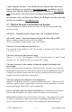
Setting Up Ditch Lights R FX3 Decoders with Right Side (Engineer's) Power Pickup DC Motor (Brushes isolated) Gray Orange Red Head Light (12V Bulb) Digitrax Decoder Right Rail (Engineer's Side) Black Left Side (Fireman's) Power Pick-up Motor Motor + White Yellow Rear Light (12V bulb) Left Rail (Fireman's Side) Forward light (F0 FWD) Reverse light (F0 REV) Blue Lamp Common Function 1 (F1) Violet Function 2 (F2) Filament lamps are recommended for ditch lights.
9.3.4 Mars Lights On F1 To set up a Mars lights: 1. Wire lamp or LED to F1 and Blue Common 2. Program CV51 to 34 3. Mars light will be on when F1 is turned ON. This will make it nondirectional and ON whenever F1 is ON no matter which direction the loco is running. 9.3.5 Rotary Beacon on F1 To set up a rotary beacon: 1. Wire lamp or LED to F1 and Blue Common 2. Program CV51 to 038 3. Rotary beacon will be on when F1 is turned ON.
9.3.7 Rule 17 AND Forward Ditch Lights To set up a rule 17 dimming & forward ditch lights on F0F, F0R & F2: 1. Wire lamp or LED to F0F and Blue Common 2. Wire lamp or LED to F0R and Blue Common 3. Wire lamp or LED to F1 and Blue Common 4. Wire lamp or LED to F2 and Blue Common 5. Program CVs to the values in the table below.
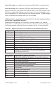
9.4 Tables for Determining FX3 CV Values Choose a value from TABLE XI:FX3 Effect Table and a value from TABLE XII: FX3 Operational Characteristics Table. Add these two numbers together to determine the CV value to program into the CV associated with the output you are using to achieve the effect and operational characteristics you want to use.
TABLE XII: FX3 Operational Characteristics Table How the FX3 Effect Generated Will Operate Value to Add for CV Value Computation for FX3 0 Forward direction, ON with function ON, effect phase A* 16 Reverse direction, ON with function ON, effect phase B* 32 Non directional effect, ON with function ON, effect phase A* 48* Non directional effect, ON with function ON, effect phase B* 64* Forward direction, ON with F0 ON & function ON, effect phase A* 80* Forward direction, ON with F0 ON & function ON
CV62 also controls how fast/slow the programmed effect operates. This lets you adjust the flashing rate of the lights. The settings in CV62 affect all function outputs on the decoder. The default value for CV62 is 00 for no keep alive brightness and fastest function operation rate. Use our online CV calculator at www.digitrax.com/support/cv to compute the CV values for your specific situation. Or use the following table to determine the appropriate CV value for CV62.
9.7 Troubleshooting FX effects Common problems with FX set up are: Trying to program a decoder for FX when the decoder does not support FX. Be sure the decoder you are installing has FX features. Digitrax introduced FX in the summer of 1995 so if your decoder was made before then it does not have FX capability. Since 1995 all Digitrax premium decoders have included FX. Digitrax standard and economy decoders do not have FX features. FX effects don’t work as expected.
A 12 or 14 volt lamp run directly without resistors will be less sensitive to voltage fluctuations. For regular 12 to 16 volt lamps that draw more than 50 mA when lit, we recommend that you put a 22 to 33 ohm 1/4 watt resistor in series with the lamp leads. This will ensure that the lamp “start-up currents” (up to 10 times normal current draw) do not overload the outputs.
9.11 Advanced Consist Function Controls CV21 & CV22 CV19 is the advanced consist address. When it is active, the functions within the advanced consist are individually controlled at their individual locomotive addresses. CV21 & CV22 allow you to place specific functions under the control of the advanced consist address instead of the individual locomotive addresses.
were one attached to the decoder. On the following table, a l in any column indicates the default throttle function control key that controls the decoder function output. More than one function output can be mapped to be controlled by a single throttle function control key. All mapping combinations are not available, only the ones shown on the TABLE XVIII below.
9.12.1 Function Mapping Example The following example shows how to map functions as follows: F0 non-directional controlling both White & Yellow Outputs F1 controls Green F2 and F8 control Violet. Turns Violet ON when either F2 or F8 is ON.
10.0 Decoder Utility CVs The decoder utility CV group handles decoder reset to factory default CV values, decoder lock for programming when multiple decoders are present in a locomotive and decoder ID information. 10.1 Factory Reset CV: 08 CV08 is the factory reset CV for all FX3 decoders. For Series 3, 4, 5, & 6 decoders, reset all CV values to their factory default, program CV08 to a value of 008. This will also cause sound projects to revert to the factory installed project.
Digitrax recommends using the following values for CV16 for consistency: 0: Factory Default Value-Decoder is not locked 1: Motor decoder 2: Sound decoder 3: Function-only decoder (e.g. for additional lights) 4-7: Additional Decoders installed in the locomotive. CV15 selects the target decoder that will accept programming commands. When the values in CV15 and CV16 are equal, all CVs in the target decoder can be programmed. When the values in CV15 and CV16 are not equal, only CV15 can be programmed.
capable decoder(s). In this case, program the decoders with the lock feature first, locking each one when programming is complete, and leave the non-lockable decoder to be programmed last. To access a decoder after installation: 1. When you want to program CVs in the target decoder with ID XX again, unlock it by programming CV15 to match the ID XX programmed in CV16. In the case of the example decoder, program CV15 to 02. 2. Once the decoder is unlocked, program CVs as desired. 3.
Using Digitrax SoundLoader and your PR3 Xtra, you can change the sound projects your decoder plays. SoundLoader runs on your PC and connects to your sound decoder using the Digitrax PR3 Xtra programmer. With SoundLoader you can easily manage the sound project files your decoders uses. If you simply want to browse inside sound projects, you can use SoundLoader without a PR3. 11.
waves that are “out of phase”. This minimizes sound cancellation, particularly at lower frequencies. For best sound generation, the cubic volume of the baffle should be as large as possible and the baffle walls should be acoustically rigid to prevent acoustic interference. Practical baffle materials are plastic, cardboard and sheet metal. Common items such as cardboard tubes, soda caps, or 35mm film canisters can be modified to create reasonable baffles in the available space inside your locomotive.
Consult the instruction sheet provided with your decoder or the project description area of the sound project (.spj) file you have loaded into the decoder to determine how CVs are used in the specific decoder and in the specific sound project file. For more information on general decoder installation and programming techniques and examples visit www.digitrax.com. CAUTION: Programming track voltage must not exceed 16V when programming SoundFX decoders. 11.
11.5 Diesel Notching CV132 & 155 Sound CV155 customizes diesel engine notching and CV132 controls notching rate. TABLE XIX: Diesel Notching CVs CV# CV Value Effect CV155 00 default Automatic notching Changes diesel RPM settings at 8 distinct throttle speeds controlled by CV132 CV155 01 Semi-automatic notching. F6 ON increases current notch setting.
11.7 Bell and Air Effect Rates CV146-149 CV146 controls the bell rate or time between ring of the bell, it has a range from 1-100 with each increment adding 24ms of delay. CV147 controls the air drier rate, it has a range from 1-64 with each increment adding approximately 2 seconds. CV148 controls the Compressor/ Air pump start rate. CV148 controls the Compressor run rate. CV149 controls how long the Compressor/Air Pump runs. 11.
TABLE XX: SDXH166D Sound Scheme Selection with CV60 Example CV60 set to Sound Scheme CV150 set to CV157 set to 0 GP38 Diesel 0= default 1-7= alt horns 128-135 = Playable horns 0=default 1-3 = alt bells 1 GE Evolution Diesel 1= default 0-7= alt horns 128-135 = Playable horns 0=default 1-3 = alt bells 2 SD70 Diesel 2= default 0-7= alt horns 128-135 = Playable horns 0=default 1-3 = alt bells 3 GP10 Diesel 3= default 0-7= alt horns 128-135 = Playable horns 0=default 1-3 = alt bells 4 RS1 Di
CV# Used For Range Default Value 01 11 2 Digit Address 03 Sound Time Out, 06 = Sound ends when loco address is de- 06 selected, 00=Sound stays on after loco is de-selected Configuration Register - Advanced or Standard speed steps, 2 29 or 4 digit addressing, Analog Mode, Normal direction of travel, 06 speed tables 49 Forward Light (F0F) - Headlight 00 50 Reverse Light (F0R) - Reverse Light 00 51 Function 1 00 52 Function 2 00 58 Master Volume (F8 used for Mute) 1=min 00=max 00-15
Function Used For F0 Lights Notes F1 Bell F2 Horn/Whistle CV150 sets mode F3 Coupler crash Auto coupler/brake set by CV151 max speed F4 Air feature disable F4 off enables pop-off, drier and starts compressor/ air pump F5 Diesel = Dynamic brake Fans Steam = Water Pump turbine F6 Diesel = Notch Up Steam = Blow down Notch UP if CV155=01 or 02 F7 Crossing Gate Air horn OR Diesel = Notch DOWN Steam = Wheel slip Notch DOWN, if CV155 = 01 OR 02 (Crossing Gate active if in Diesel mode and CV1
actual sound recording you’ve made. You do this with the SoundLoader utility in conjunction with a Digitrax PR3 programmer. Once you’ve customized the project, you can save the sound project (.spj) file with a new name. This will let you use your custom project over and over again. We encourage you to share your customized sound projects with other modelers by submitting them to the Sound Depot at www.digitrax.com/sound-depot/submit/.
view>project description” menu and then read the text file on the screen that defines how that project in particular uses CVs and functions for sound generation and configuration. 12.0 Operation With Digitrax Command Stations Digitrax decoders support direct and paged programming. Digitrax decoders are designed to operate with command stations that are compatible with DCC industry standards.
plug converts the locomotive to DC operation only. Locomotives with the dummy plug will run on conventional layouts without sacrificing low speed performance and can run using pulse power. To run the loco on DCC again, remove the dummy plug & re-install the decoder. 14.0 Decimal & Hex Numbers Digitrax produced our first throttles in 1992. Many of these throttles are still in use on layouts today.
complete the online form, print it out and send it in with your items for repair. Proof of date of purchase is required for all warranty repairs. In some cases with Digitrax lower cost decoders, the cost to purchase a new decoder may be less than the repair charge. Also some older models are no longer repairable or replaceable due to unavailability of components needed for these repairs.
Index Symbols 2 Digit Address 30–31, 34, 35, 36, 39, 44, 66, 77 4 Digit Address 31, 35, 38 A Acceleration 16, 25, 30, 32, 37, 40 Address “00” 35 Air Effects 75 Analog Mode Conversion 24, 31, 36, 37, 44, 78 DCC Functions on DC 37 B Back EMF Amount (Intensity) 33, 47 Back EMF-Scaleable Speed Stabilization 7, 8, 33, 43, 47, 48, 49 Bell 73, 75, 76 Board Replacement Decoder 12, 13 Brake Generator Example 37 C Cam Input 72 Capacitor 10, 12, 17, 51, 70 Choosing a Locomotive 9 Choosing The “Right” Decoder 10 Chu
D DCC Ready Locomotive 12 DC Decoder Operation 78 DC Sound Operation 76 Deceleration 16, 28, 30, 37, 40 Decoder ID CVs 68 Decoder Lock 32, 34, 46, 47, 66 Decoder Part Numbering System 7 Decoder Programming 28 Direct Programming Mode 28 Operations Mode Programming 28, 29, 70 Paged Mode Programming 28 Physical Register Mode Programming 29 Service Mode Programming 28 Diesel Notching 72 Digitrax On-Line Decoder Selector 10 Direct Programming Mode 28 Ditch Lights 54–60 Dummy Plug 78 Dynamic Compensation Back EMF
Directional Lights 7, 15, 23, 56, 57, 59, 62, 65 Ditch Lights 33, 54, 55, 57, 59, 60 Gyralite 58 Headlight 23, 52, 58 Master Light Switch 17, 52, 61 Rotary Beacon 56 Rule 17 Dimming 56 Strobe Lights 57, 58 Lock Decoder 32, 34, 46, 47, 66 LocoMotion 16, 32, 40, 47 LocoNet Cable Tester-LT1 18, 19, 27 M Master Light Switch 17, 52, 61 Medium Plug/Socket 12 Motor Isolation 9, 21–22 Multiple Decoders in One Loco 32, 34, 46, 47, 66 N Normal Direction of Travel 31, 75 O Operations Mode Programming 29, 70 P Page
Service Mode Programming 28 SoundDepot 76 SoundFX Decoders 5, 17, 23, 68–71, 74, 76–77 SoundLoader 69, 74, 76, 77 Sound Projects 5, 25, 30, 66, 68, 69, 71, 76, 77 Sound Schemes 70, 73 Speakers & Baffles 69 Speed Tables Loadable Speed Tables 25, 31, 36, 39, 41, 42, 43, 44, 46 Three Step Simple Speed Table 32, 42, 43–45 Throttle Response Curve 41 spj 71, 73, 74, 76, 77 Stall Current 10–11 Static Compensation Back EMF 33, 47, 49, 62 Steam Chuff 72, 75 Strobe Lights 57, 58 SuperSonic (Quiet Operation) 33, 52 Sw
This page [is] intentionally left blank. © 2017 Digitrax, Inc. - 85 - www.digitrax.
C omplete T rain C ontrol Need Help? Digitrax Tech Support Team Need Help?: helpdesk.digitrax.com Digitrax Tech Support Depot 24/7/365 www.digitrax.com/support Contains links to all instructions sheets and manuals, application notes, videos and tons of helpful information. Digitrax Decoder Selector www.digitrax.com/decoderselector Helps you find which decoder will fit in a particular locomotive. Digitrax CV Calculators www.digitrax.