
Inc Sound Module Decoder - Manual


© 2017 Digitrax, Inc.
www.digitrax.com- 19 -
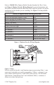
LT1 Decoder Testing Instructions
1. Strip the insulation from the red and yellow wires and twist them
together.
2. Strip the insulation from the green and black wires and twist them
together.
3. The blue and white wires are not used. They can be left on the har-
ness.
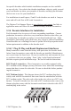
4. Hook up decoder as shown here. If your decoder does not have wires,
use alligator clips to make the appropriate connections to the pads or
pins on your decoder.
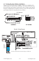
5. Use your throttle to select the decoder and run it in the forward direc-
tion.
6. One of the two center LEDs will light as the motor voltage increases.
Change direction and the other LED will light.
7. Test the decoder function outputs by connecting the LT1 to the blue
lamp common and one of the function outputs.
8. Use your throttle to turn the function on and off . One of the two cen-
ter LEDs will go on and off with the function. Do this test for all
function outputs separately.
Note: The LT1 can also be used to test LocoNet Cables by plugging in
one end of the cable being tested into the LT1 and the other end into
your command station or booster. At least one Digitrax throttle or
Zephyr all-in-one unit must be plugged in to LocoNet. If all four
LEDs light, the cable is good. Note that the LEDs may not all be
the same brightness, this is normal. If any of the LEDs fail to light,
remove the plug from on end of the cable and re crimp another one
prior to re-testing the cable. Digitrax LocoNet Cable Maker Kit has
everything you need to make repairs to LocoNet Cables.