Mark III Directional Drilling Locating System Operator’s Manual DIGITAL CONTROL INCORPORATED DCI Headquarters DCI Europe www.digitrak.com Kurmainzer Strasse 56 D-97836 Bischbrunn Germany Tel +49(0) 9394 990 990 Fax +49(0) 9394 990 999 DCI.Europe@digital-control.com 19625 62nd Ave. S., Suite B-103 Kent, Washington 98032 USA Tel 425 251 0559 / 800 288 3610 Fax 253 395 2800 E-mail DCI@digital-control.
DIGITAL CONTROL INCORPORATED ® 3-3000-00-F © 1999-2006 by Digital Control Incorporated. All rights reserved. July 2006 Edition. Trademarks The DCI logo, CableLink®, DataLog®, DigiTrak®, Eclipse®, iGPS®, Intuitive®, look-ahead®, SST®, target-inthe-box®, and Target Steering® are U.S. registered trademarks and DucTrak™, FasTrak™, SuperCell™, LT™, TeleLock™, and TensiTrak™ are trademarks of Digital Control Incorporated. Patents The DigiTrak® Locating System is covered by one or more of the following U.S.
® DIGITAL CONTROL INCORPORATED Table of Contents SAFETY PRECAUTIONS AND WARNINGS .................................................................................. vi INTRODUCTION ..............................................................................................................................1 Basic DigiTrak Equipment ...................................................................................................1 Basic DigiTrak Operation....................................................
DIGITAL CONTROL INCORPORATED ® Table of Contents (Cont.) REMOTE DISPLAY SYSTEM ........................................................................................................25 On/Off and Setting the Channel ........................................................................................26 Transmitter Temperature and Battery Status ....................................................................26 Remote Steering.........................................................................
® DIGITAL CONTROL INCORPORATED Table of Contents (Cont.) LOCATING (Cont.) Calculating Depth Based on Distance Between FNLP & RNLP .......................................52 Running Off Pitch or Calculating Depth from Pitch ...........................................................53 Transmitter’s Signal Shape ...............................................................................................54 Antennae Configuration...............................................................................
DIGITAL CONTROL INCORPORATED ® Safety Precautions and Warnings Important Note: All operators must read and understand the following Safety Precautions and Warnings before using the DigiTrak Locating System. 1 Serious injury and death can result if underground drilling equipment makes contact with an underground utility such as a high-voltage electrical cable or a natural gas line.
® DIGITAL CONTROL INCORPORATED Safety Precautions and Warnings (Continued) ¾ Prior to the start of each drilling run, test the DigiTrak System to confirm that it is operating properly and check that it is providing accurate drill head location and heading information (see Receiver Section) and accurate drill head depth, pitch, and roll information with the Transmitter inside the drill head.
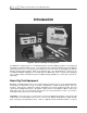
DIGITAL CONTROL INCORPORATED ® Dear Customer: We would like to thank you for choosing the DigiTrak Locating System. We are proud of the equipment that we have been designing and building in Washington State since 1990. We believe strongly in providing a unique, high-quality product and standing behind it with superior customer service and training. We ask that you take the time to read this entire manual—especially the section on safety.
® DIGITAL CONTROL INCORPORATED Introduction Receiver DataLog Module Remote Display Transmitters Battery Charger Cable Transmitter DigiTrak® Directional Drilling Locating System The DigiTrak Locating System is used during horizontal directional drilling operations for locating and tracking the transmitter within the tool. This manual provides detailed information about the DigiTrak System and how to use it.
Introduction ® the optional cable transmitter, which requires a 12V to 28V DC system. For gravity sewer installations, DCI manufactures a sensitive-pitch transmitter that measures pitch in 0.1% increments. Remote Display – The DigiTrak Remote Display unit enables the drill operator to view the transmitter’s pitch, roll, depth, predicted depth, and temperature, and can also be used for remote steering when walkover tracking is not possible.
® Introduction Operational Tests – Before drilling and during operation it is necessary to check the following: proper calibration, correct ultrasonic measurement, status of battery power, transmitter temperature, and signal interference problems. (see Operational Tests Section) Locating – The DigiTrak System is used to locate the transmitter underground; the trigger under the receiver’s handle is held in during locating to show signal strength in the upper left window.
Introduction ® Notes 3-3000-00b-F 4 DigiTrak® Mark III Operator’s Manual
® DIGITAL CONTROL INCORPORATED Receiver Handle Speaker Trigger Display Windows Temperature & Distance Conversion Chart Depth/Locating Antenna Screws Battery Compartment Back Panel Front Panel Pitch/Roll Antenna Screws DigiTrak Receiver – Side View The DigiTrak Receiver is a hand-held unit used for locating and tracking the transmitter.
® Receiver Display Window Icons Trigger down – Trigger is released; display windows show pitch, roll, and distance/depth of the transmitter. +% -% 12 9 3 6 x Pitch – Numbers from 0% to ±100% show the inclination of the transmitter with respect to horizontal; 100% represents a 45° angle (top left window, trigger down). Roll – Numbers from 1 to 12 show the roll position (1 o’clock to 12 o’clock) of the transmitter (top right window, trigger down).
® Receiver respectively). If there is an orange arrow below the serial number, then it is a remote receiver, and it is capable of sending a signal to a remote display unit at the drill. All receivers can be upgraded to remote capability. The Mark III Receivers (serial numbers greater than 4676) are also equipped with a backlit display for dim viewing conditions. All receivers can be upgraded to have a backlit display. DigiTrak equipment is like a computer in that it requires firmware.
® Receiver The depth measurement units (centimeters or inches) and remote channel setting can be changed only during start-up (see “Changing Depth Measurement Units” and “Changing the Channel Setting” below). After the start-up process, the windows will display pitch, roll, and distance if there is an active transmitter within range (see Tracking Mode display below). If an active transmitter is not within range, 1999 will appear in the bottom window and the top windows will be blank.
® Receiver For receivers that have pre-5.0 series firmware, the bottom window will continue to display the receiver’s distance from the transmitter in the bottom window, not the predicted depth. (For more information, see “5.0 Series Firmware Functions” in this section or see the Locating Section.) Any time the trigger is clicked (pushed in and released in less than ½ second), the receiver will initiate an ultrasonic measurement, which is also referred to as the height-above-ground measurement.
® Receiver Changing the Depth Measurement Units (English vs. Metric) The DigiTrak Receiver is capable of displaying depth in either inches (English) or centimeters (metric). The depth measurement units can only be changed during the start-up process. To change the measurement units: Instead of clicking the trigger to initiate start-up, simply squeeze and hold in the trigger for 12-14 seconds (the unit may or may not make a tone during this time depending upon the firmware version).
® Receiver Warning Tones for Transmitter Overheat Beginning with firmware version 3.76, the DigiTrak Receiver will emit a series of increasing warning tones to signal transmitter overheating as follows: Temperature Range Warning Signal 14°C and below No audio or visual warnings. 15°C to 35°C One double tone with every 4°C increase in temperature. 36°C to 45°C Two double tones with every 4°C increase in temperature. 45°C to 60°C Three double tones with every 4°C increase in temperature.
® Receiver Following are some general points regarding the ultrasonic function: ¾ The ultrasonic function in the receiver is independent of the transmitter receiving functions. ¾ A single click to activate the ultrasonic function can be used an unlimited number of times without affecting the receiver’s calibration. ¾ The ultrasonic measurement is held in memory until the trigger is clicked again for a new ultrasonic measurement or until the receiver turns off.
® Receiver Calibrating the Receiver There are two different calibration methods: 1-point and 2-point. The 1-point calibration is performed with the transmitter in the housing parallel to and 10 ft 5 in. (3.18 m) from the receiver, as described below. A 2-point calibration is generally performed when the transmitter is below ground and it is not possible to perform a 1-point calibration. Calibration is necessary prior to first time use and when any of the following occur: ¾ The transmitter is changed.
® Receiver 4. Click the trigger one time. 5. The receiver will beep. During the beep, pull in the trigger and hold it. 6. Continue to hold the trigger and watch the countdown (from 5 to 0) displayed in the bottom window. This countdown is accompanied by a chirping sound. 7. When the countdown reaches zero, let go of the trigger. 8. A good calibration will be confirmed by 3 short beeps.
® Receiver 5. During the tone, click the trigger again and continue to hold the receiver level and steady. You will then hear 2 beeps followed by a long 6-second tone, indicating that the first calibration point is found. 6. During the 6-second tone, raise the receiver straight up, keeping it level and in the same plane above the transmitter, as high as you comfortably can. Before the 6-second tone ends you must steady the receiver and click the trigger. 7.
® Receiver Calibrating with Transmitter Underground at Shallow Depth (< 10 feet) Should recalibration be necessary when the transmitter is below ground at depths less than 10 ft (3 m), it is possible to conduct a modified 1-point calibration procedure. This requires knowing the signal strength of the transmitter in the housing at 10 ft. (You should always note the value of the signal strength when you first perform a 1-point calibration.
® Receiver Finding Firmware Version It is possible to determine the firmware version in the receiver. This information is necessary to complete troubleshooting diagnostics with DCI Customer Service by telephone. At start-up the firmware version is displayed briefly in the top left window. If you do not see the firmware version, it is likely that you have an older receiver.
® Receiver Procedure for Observing the Predicted Depth When the receiver (with 5.0 firmware) is at the FNLP and held level with the trigger in, the bottom window will rapidly flash the predicted depth number accompanied by a solidly lit squiggle (“~”); the predicted depth information is also displayed in the bottom window on the remote display. Should the trigger be held in at any other location than the FNLP, the predicted depth in the bottom window will be invalid and should be disregarded.
® DIGITAL CONTROL INCORPORATED Transmitter Batteries Antenna Index Slot Front Back DigiTrak Transmitter A transmitter (also referred to as a sonde, beacon, or probe) is a device that emits electromagnetic signals at radio frequencies and fits inside the tool housing. It transmits information regarding its location, position, and heading. The transmitter emits signals that the receiver “hears” and converts into the information shown in the three display windows.
® Transmitter Transmitter roll positions are displayed digitally as a whole number from 1 through 12 in the top right window with the receiver’s trigger released. The numbers correspond to the hour hand of a clock. At the 12 o’clock position, the transmitter is oriented with the index slot at the top. The tapered or flattened surface of the drill head should be indexed to this position.
® Transmitter The temp dot should be white if the transmitter has not been exposed to excessive heat. If the temp dot is silver or gray, it indicates the transmitter has been exposed to heat but not in excess of the specifications. A black temp dot indicates the transmitter has been exposed to temperatures in excess of 104°C (220°F). The transmitter will shut off at about 80°C.
® Transmitter any free space between the transmitter and the side walls of the housing. If necessary, fabricate an “insert” behind the transmitter to ensure a snug fit. When wrapping with tape, be sure that the pitch will not be offset. If more tape is on one end than the other, the transmitter will not be level in the housing. Also, be sure that metal-to-metal contact is avoided. Before purchasing a new housing, place a transmitter inside and check for a snug fit.
® Transmitter Locating the Transmitter The properties of the transmitter’s magnetic field enable the receiver to locate the transmitter accurately below ground. The transmitter emits an elliptically shaped field that allows the receiver to locate the transmitter using three specific locations, not just the highest signal. These locations are referred to as the front and rear negative locate points (FNLP and RNLP) and the positive locate line.
® Transmitter Serial Numbers All transmitters are identified by a serial number stamped in the metal battery compartment near the plastic/stainless steel contact. NOTE: When calling DCI Customer Service be prepared to supply the serial number. Specifications The specifications given below assume the use of the latest model (Mark III) of the DigiTrak Receiver. All Mark III Transmitters operate at a frequency of approximately 33 kHz. Pitch updates occur every 2.5 seconds, and roll updates occur every 0.
® DIGITAL CONTROL INCORPORATED Remote Display System Pitch or Battery Status Roll or Temperature ~ Depth/Distance or Predicted Depth I5 Remote Steering Window 8 I I8 Channel Selector Mounting Screws for DataLog Module On/Off Button Remote Display Unit The DigiTrak Remote Display unit is typically positioned where it will be readily visible by the drill operator. The remote display uses telemetry to display some of the information displayed by the receiver.
® Remote Display On/Off and Setting the Channel To turn the unit on, place a fully charged DigiTrak battery pack into the battery compartment, terminal end in first, then push the black button on the front of the display panel. Select one of the four channels. Note that channels 1 and 3 use one frequency, and channels 2 and 4 use a second frequency.
® Remote Display Remote Steering Remote steering is used to cross streams and roadways or other inaccessible areas when it is not possible to walk over the transmitter. To initiate the remote steering capability, the receiver is placed in front of the transmitter as the “target.” The distance the receiver can be placed ahead is limited by the range of the transmitter and interference.
® Remote Display Vertical Bar (Represents Transmitter) ~ I5 Steering Triangles (Represent Receiver) 8 I I8 Align Vertical Bar (Transmitter) with Triangles (Receiver) in Remote Steering Window to Steer Tool As the transmitter approaches the target (receiver), the FNLP will pass underneath and go past the receiver. At this point, the remote steering is no longer accurate and the receiver must be moved to a new farther-out location.
® DIGITAL CONTROL INCORPORATED Battery Charger DigiTrak Battery Pack Unexposed Terminal -- Do Not Expose -DC Power Cord AC Power Cord Negative Terminal Positive Terminal Control Panel DigiTrak Battery Charger Both the DigiTrak Receiver and the Remote Display use a DigiTrak rechargeable NiCad battery pack that is provided with the system together with a DigiTrak Battery Charger. The battery pack should be fully discharged before recharging; this is known as conditioning the battery.
® Battery Charger Only two terminals are exposed on the DCI NiCad battery pack, although a third terminal appears to be available. If the third terminal accidentally becomes exposed, do not try to charge the battery pack or you may damage the battery charger. Such a battery can also damage the remote display or receiver. A damaged battery pack will require replacement. Charging a Battery NOTE: Only charge DigiTrak NiCad batteries in the battery charger.
® Battery Charger Conditioning a Battery in the Charger 1. Place the battery into the charger. 2. Press the right button on the charger (marked with a curved arrow). The red light on the left will go out and the green light on the right will start to blink. This indicates that the battery is being conditioned. The conditioning cycle may last for up to 7 hours, depending on the remaining charge in the battery. 3.
Battery Charger ® Notes 3-3000-00f-F 32 DigiTrak® Mark III Operator’s Manual
® DIGITAL CONTROL INCORPORATED System Operating Instructions Start-up Procedure 1. Ensure that the transmitter has fresh C-cell alkaline batteries installed and place the transmitter inside the tool housing. 2. Click the receiver trigger, located under the handle. All the displays will illuminate, and a tone will sound. 3. Ensure that the receiver’s battery pack does not indicate low battery power (bottom window would display “BAT”). 4.
® System Operation Optimal Operating Temperatures The minimum operating temperature for the DigiTrak locating equipment is -4°F (-20°C). All batteryoperated equipment is prone to “capacity loss” in cold temperatures. Excessively cold temperatures can result in slow display response and increased measurement errors. The maximum temperature for receivers and remote displays is 176°F (80°C). Operation in direct sunlight can cause temperatures greatly in excess of the air temperature.
® DIGITAL CONTROL INCORPORATED Signal Interference Before drilling (preferably before bidding on a project) the interference potential at your site(s) should be evaluated. Interference can reduce the transmitter’s range or cause variable readings and possibly result in job slowdowns. Interference comes from two different types of sources: active and passive. Active interference is also known as electrical interference or noise and can have varying effects upon the DigiTrak locating equipment.
® Signal Interference There are two steps to the electrical interference/background noise check. The first step takes one person; the second step requires two people. 1. With the transmitter off, test the amount of noise the receiver hears by holding in the trigger and walking the borepath from the launch to the exit location. Watch the signal strength (top left window) and note the locations where the signal strength changes.
® DIGITAL CONTROL INCORPORATED Operational Tests Self-Test for Mark III Receivers Mark III Receivers have the capability of completing a diagnostic self-test to confirm proper operation. This test must be conducted without a transmitter and in an interference-free environment. The self-test procedure is conducted at start-up by clicking the trigger in a specific sequence. 1. Place a fully charged DigiTrak battery into the receiver and click the trigger once. 2.
® Operational Tests 3. Walk toward the axis line and watch for the plus (“+”) sign in the top left window to change to a minus (“–”) sign. Note this location. 4. Continue past the axis line, then stop and turn the receiver 180° around so it is facing in the opposite direction. Walk back toward the axis line from this opposite side and find the location where the “+” changes to a “–”. 5. These two locations should be in the same place and lie on the axis line. assistance.
® ¾ Operational Tests Defective Transmitter – With the transmitter and receiver on, place the transmitter against the receiver (long side of transmitter parallel to long side of receiver) while holding in the trigger. If you see anything less than 999 in the top left window and 000 in the bottom window, it is likely that there is a broken antenna in the transmitter. You will need a new transmitter.
® Operational Tests ¾ Battery Life – Verify the housing slots (windows) are properly aligned over the transmitter’s antenna. If the battery life of a transmitter seems to be shorter than that noted in the specifications provided in the Transmitter Section, it could be due to battery arcing, which can occur in hard drilling conditions. transmitter batteries arc when they bounce/slam into each other, losing contact intermittently.
® Operational Tests Transmitter Battery Tests ¾ The design of the windows/slots in a housing can greatly affect the transmitter’s battery life, especially on the red long-range DX Transmitters. The windows must be a minimum of 8 inches (20 cm) long and line up longitudinally along the drill housing, directly above the center of the transmitter. (Drawings are available upon request.) A minimum of five slots, equally spaced around the diameter of the housing, are required.
Operational Tests ® Notes 3-3000-00i-F 42 DigiTrak® Mark III Operator’s Manual
® DIGITAL CONTROL INCORPORATED Locating Locating Mode To locate the transmitter the receiver’s trigger must be held in. This is referred to as the “locating mode”. When the trigger is held in, the top left window will stop displaying pitch with the flashing pitch/roll update squiggle (“~”) and will instead display signal strength and the “+/–” indicator.
® Locating Handling the Receiver For the most accurate locating, the receiver must be held level and parallel to the transmitter. The receiver can be held so that it faces in the same direction as the transmitter or in the opposite direction (see sketch). Receiver parallel to Transmitter and facing in opposite direction The front and rear negative locate points are denoted as such because each is at a point where the sign changes from positive to negative.
® Locating In summary, the three locations mentioned above are as follows: the rear negative locate point (RNLP), behind the transmitter; the positive locate line, above the transmitter; and the front negative locate point (FNLP), ahead of the transmitter. The RNLP and the FNLP show the position and lateral orientation of the transmitter. Using Plus/Minus Indicators for Locating The “+” and “–” signs indicate the direction to move the receiver to locate the transmitter.
® Locating 2. To determine the lateral and therefore the actual location of the RNLP, turn toward the left so that the receiver is perpendicular (90°) to the drill string and move the receiver forward. Again, move the receiver slightly forward and backward until pinpointing the location where the “+/–” signs flip from one to the other. PLL Plus Changes to Minus Fine Tuning the RNLP Location (Walking Toward Left) Drill Finding the Positive Locate Line (PLL) 3.
® Locating Finding the Front Negative Locate Point (FNLP) 4. At the PLL, continue walking away from the drill with the trigger held in; the signal strength will decrease. When the “+” sign flips to a “–” sign, this is the FNLP. Again, move the receiver forward and backward a little pinpointing the location where the “+/–” signs flip from one to the other. Plus Changes to Minus Surface of Ground Drill FNLP Transmitter Finding the Front Negative Locate Point (FNLP) from the Drill 5.
® Locating Finding the Transmitter and Its Depth 7. While standing on the FNLP facing the drill, it is possible to “sight in” or align the FNLP with the RNLP. This axis line is at a 90° angle (perpendicular) to the PLL. Where this axis line crosses the PLL is where the transmitter will be found, below ground surface. Take the receiver to the transmitter’s location and measure the depth of the transmitter.
® Locating Locating the Transmitter from the Front The transmitter’s three locations can be determined in a similar manner as described above starting in front of the transmitter while facing the drill. Start at a location well ahead of the transmitter and hold in the trigger while facing the drill. A “+” sign should appear in the top left window (along with the signal strength). Walking toward the transmitter, the “+” sign will change to a “–” sign at the FNLP.
® Locating Locating on the Fly Once you are comfortable finding the transmitter’s three locating points (FNLP, RNLP, and PLL) it is time to increase your speed at locating. Hopefully this will directly affect your productivity! 1. Mark the position of the FNLP and pace out the distance of the next drill rod (this distance will vary depending upon the pitch of the transmitter and the topography). 2. Face the drill and hold the trigger in on the receiver. A “+” sign should appear in the top left window.
® Locating 4. Step further to the side of the transmitter and again find the point where the “–” sign changes to a “+” (Point 2). 5. Repeat this procedure to find the third location (Point 3). When all three of these points are lined up, they confirm the location of the PLL, from which the heading of the transmitter can be determined, because the PLL is at a 90° angle to the transmitter. As drilling continues, the drill should be steered to maintain constant slant distances at either of Points 1, 2, or 3.
® Locating 7. Repeat steps 2 through 6 until the “+/–” signs flip from one to the other over a very small area. This is either the FNLP or the RNLP. To find the other locate point, walk in the assumed direction of drilling. If the signal strength increases you are at the RNLP; if it decreases you are at the FNLP. 8. To confirm you are over the FNLP or RNLP (as opposed to being over the transmitter), rotate the receiver (with the trigger held in) 360° at the FNLP or RNLP.
® Locating Running off Pitch or Calculating Depth from Pitch The transmitter’s depth can be estimated by using the pitch information. Use the following procedure to estimate the depth based on the pitch, starting with the first rod. 1. At the point the drill head penetrates the surface of the ground to the middle of the transmitter’s slots (entry point), measure the amount of rod left on the rack (from the make-up/breakout clamps to the top of the rod).
® Locating Transmitter’s Signal Shape It is important to understand some fundamental concepts about the transmitter’s electromagnetic signal and the way the receiver’s antennas read or receive this signal. The shape of the transmitter’s signal field is elliptical. This elliptically shaped field combined with the DigiTrak Receiver’s unique “X” antenna configuration results in locating the transmitter at three specific locations, not just the strongest/highest signal.
® Locating Field Strength: 100% 0% Field Strength: 0% 100% Parallel Field Lines and Antenna Perpendicular Field Lines and Antenna Orientation of Field Lines with Respect to Antennas >>>>>>>>>>>>>>> Front and Rear Negative Locate Points >>>>>>>>>>>>>>> If the field line is vertical with respect to the antennas, each antenna will read 50% of the signal (figure).
Locating ® Notes 3-3000-00j-F 56 DigiTrak® Mark III Operator’s Manual
® DIGITAL CONTROL INCORPORATED Cable Transmitter System Power Supply Remote Display Cable Transmitters Extraction/Insertion Tool DigiTrak Cable Transmitter System The DigiTrak Cable Transmitter System is designed specifically for the following applications: ¾ Borepaths with depths in excess of 50 ft (15 m). ¾ Borepaths with lengths that require several days to drill. ¾ Borepaths that do not allow walkover locating. ¾ Borepaths in high-interference areas.
® Cable Transmitter Remote Display with Cable Transmitter Capability – This is a remote display that has been upgraded or was originally built to display the cable transmitter data. During operation with a cable transmitter, a delta symbol (Δ) illuminates in the top left window indicating the cable mode. All “cable-ready” remote displays have a label near the battery compartment door that indicates it is configured to receive the cable transmitter’s information (see photo).
® Cable Transmitter Power Supply The Cable Transmitter Power Supply plugs into the remote display where a regular DCI battery pack is normally placed. The power supply has three wires extending from it. The green and black wires should be connected to a DC power source (green is positive, black is negative). The white wire is connected to the cable transmitter (see sketch later in this section called “Connecting Cable Transmitter to Power Supply and Remote Display”).
® Cable Transmitter Cable Transmitter The cable transmitter has the same general features and capabilities as the other DigiTrak Transmitters but with increased depth range. The dimensions of the cable transmitter are the same as those of the 2cell DigiTrak Transmitters (DT, DX, and DXP). However, there is also a power/signal cable extending from the rear metal grounding cap. The metal grounding cap must make solid contact with the interior of the housing, which is grounded through the drill.
® Cable Transmitter ¾ Temperature information can be accessed manually by turning off and then on the cable-ready remote display. ¾ Upon supplying power, the cable transmitter will begin transmitting data. ¾ There is no sleep mode; therefore, the power supply must be turned off manually at the end of the day. Failure to turn off the power overnight can result in an overheated cable transmitter. ¾ A low battery indication (BAT) could signify that another battery is needed.
® Cable Transmitter Viewing the Cable System Battery Status The percentage of required voltage will be displayed in the top left window of the remote display for 2 seconds when the transmitter’s temperature increases by 4°C, which will be displayed in the top right window. To manually access the voltage status, turn the remote display off and on and observe the top left window after the firmware version is displayed.
® DIGITAL CONTROL INCORPORATED Troubleshooting Problem/Concern 1999 in bottom window of receiver, indicating no signal is being received from the transmitter. Causes/Solutions Transmitter is asleep (wake it up by rotating the drill string). Dead batteries in the transmitter. Broken transmitter. Overheated transmitter. Section to Consult “Electrical Interference/ Background Noise Check” in Signal Interference Section Transmitter Section Transmitter is out of range of receiver.
® Troubleshooting Problem/Concern Remote display has dashes across windows. (Continued) Causes/Solutions Section to Consult Interference is interrupting the signal from the receiver. Line of sight between receiver and remote display may be obstructed (by such things as buildings, hills, or dense vegetation). “Electrical Interference/ Background Noise Check” in Signal Interference Section Remote Display Section Receiver is not equipped to send a signal back to a remote display.
® Troubleshooting Problem/Concern Erratic depth. Causes/Solutions Interference. Transmitter is off. If possible, try another receiver or transmitter to identify the problem. The approximate depth may be calculated using the pitch information and the distance between the FNLP and RNLP. Transmitter exits further to the left or right than receiver indicated.
® Troubleshooting Problem/Concern Minus sign (“–”) in bottom window. Causes/Solutions Section to Consult Receiver is set on ground for depth reading, particularly at shallow depths, and the ultrasonics are not reset. Reset the ultrasonics. “Ultrasonic Function” in Receiver Section “Calibrating the Receiver” in Receiver Section Receiver has gone out of calibration. Recalibrate using either 1-point or 2-point calibration. Roll positions sticking or not accurate.
® Troubleshooting Problem/Concern Ultrasonics don’t work. Causes/Solutions Check ultrasonic holes on bottom of receiver for mud or debris. If dirty, carefully clean them out. Be extremely careful not to puncture the metal inside the ultrasonic holes. Use isopropyl alcohol (99% by volume) in modest amounts; swish around (upside down) and fling out the liquid. Repeat two more times and allow to dry for about 15 minutes.
Troubleshooting ® Notes 3-3000-00l-F 68 DigiTrak® Mark III Operator’s Manual
® DIGITAL CONTROL INCORPORATED Glossary Active Transmitter A transmitter that has batteries installed or a cable transmitter that is hooked up to power. Battery Charger Used to charge and condition (discharge) the DigiTrak batteries. May be used with AC or DC sources and is easily adapted for worldwide usage. Cable Transmitter Transmitter that is hard wired directly to the remote display unit and allows information to be obtained during very long and/or deep drilling runs. Clicking vs.
® Glossary Housing = Drill Tool = Drill Head The downhole device into which the transmitter fits. Locate Line and Points See Positive Locate Line, Front Negative Locate Point, and Rear Negative Locate Point. Magnetic Distance The magnetic distance is used by the receiver to calculate the depth/distance of the transmitter. For more information see “Ultrasonic Function” in the Receiver Section.
® Glossary Remote Display A device at or near the drill rig used to display the transmitter’s information communicated from the receiver. This device can be used for remote steering when walkover locating is not possible. Roll The rotation about the longitudinal axis of the transmitter. Set the Ultrasonics To set the ultrasonics, click the trigger once and observe the bottom window. The number displayed for 2 seconds will now be subtracted from the total magnetic distance.
Glossary ® Ultrasonic Distance = Ultrasonic Measurement = Height-Above-Ground Measurement The receiver’s height above the ground, which is displayed in the bottom window for 2 seconds after the trigger is clicked. The ultrasonic measurement is used to accommodate the different heights of drillers. For more information see “Ultrasonic Function” in the Receiver Section.
® DIGITAL CONTROL INCORPORATED Appendix The information and tables contained in this appendix provide further assistance for confirming the position of the Transmitter. The following information is provided: Depth Increase in Inches per 10-foot Rod Percent of Grade to Degree Conversions (1% Pitch Transmitters) Percent of Grade to Degree Conversions (0.1% Pitch Transmitters or Sensitive Pitch) Degree to Percent of Grade Conversions (1% Pitch Transmitters) Degree to Percent of Grade Conversions (0.
® Appendix Depth Increase in Inches per 10-foot Rod 74 Percent Depth Increase Percent Depth Increase 1 1 27 31 2 2 28 32 3 4 29 33 4 5 30 34 5 6 31 36 6 7 32 37 7 8 33 38 8 10 34 39 9 11 35 40 10 12 36 41 11 13 37 42 12 14 38 43 13 15 39 44 14 17 40 45 15 18 41 46 16 19 42 46 17 20 43 47 18 21 44 48 19 22 45 49 20 24 50 54 21 25 55 58 22 26 60 62 23 27 70 69 24 28 80 75 25 29 90 80 26 30 100 85 Di
® Appendix Percent of Grade to Degree Conversions (1% Pitch Transmitters) Percent Degree Percent Degree Percent Degree Percent Degree 1 0.6 26 14.6 51 27.0 76 37.2 2 1.1 27 15.1 52 27.5 77 37.6 3 1.7 28 15.6 53 27.9 78 38.0 4 2.3 29 16.2 54 28.4 79 38.3 5 2.9 30 16.7 55 28.8 80 38.7 6 3.4 31 17.2 56 29.2 81 39.0 7 4.0 32 17.7 57 29.7 82 39.4 8 4.6 33 18.3 58 30.1 83 39.7 9 5.1 34 18.8 59 30.5 84 40.0 10 5.7 35 19.
® Appendix Percent of Grade to Degree Conversions (0.1% Pitch Transmitters or Sensitive Pitch) 76 Percent Degree Percent Degree Percent Degree Percent Degree 0.1 0.1 2.6 1.5 5.1 2.9 7.6 4.3 0.2 0.1 2.7 1.5 5.2 3.0 7.7 4.4 0.3 0.2 2.8 1.6 5.3 3.0 7.8 4.5 0.4 0.2 2.9 1.7 5.4 3.1 7.9 4.5 0.5 0.3 3 1.7 5.5 3.1 8 4.6 0.6 0.3 3.1 1.8 5.6 3.2 8.1 4.6 0.7 0.4 3.2 1.8 5.7 3.3 8.2 4.7 0.8 0.5 3.3 1.9 5.8 3.3 8.3 4.7 0.9 0.5 3.4 1.9 5.
® Appendix Degree to Percent of Grade Conversions (1% Pitch Transmitters) Degrees Percent Degrees Percent 0 0.0 23 42.4 1 1.7 24 44.5 2 3.5 25 46.6 3 5.2 26 48.8 4 7.0 27 51.0 5 8.7 28 53.2 6 10.5 29 55.4 7 12.3 30 57.7 8 14.1 31 60.1 9 15.8 32 62.5 10 17.6 33 64.9 11 19.4 34 67.5 12 21.3 35 70.0 13 23.1 36 72.7 14 24.9 37 75.4 15 26.8 38 78.1 16 28.7 39 81.0 17 30.6 40 83.9 18 32.5 41 86.9 19 34.4 42 90.0 20 36.
® Appendix Degree to Percent of Grade Conversions (0.1% Pitch Transmitters) 78 Degrees Percent Degrees Percent 0.1 0.2 3.1 5.4 0.2 0.3 3.2 5.6 0.3 0.5 3.3 5.8 0.4 0.7 3.4 5.9 0.5 0.9 3.5 6.1 0.6 1.0 3.6 6.3 0.7 1.2 3.7 6.5 0.8 1.4 3.8 6.6 0.9 1.6 3.9 6.8 1 1.7 4 7.0 1.1 1.9 4.1 7.2 1.2 2.1 4.2 7.3 1.3 2.3 4.3 7.5 1.4 2.4 4.4 7.7 1.5 2.6 4.5 7.9 1.6 2.8 4.6 8.0 1.7 3.0 4.7 8.2 1.8 3.1 4.8 8.4 1.9 3.3 4.9 8.6 2 3.5 5 8.
® Appendix Calculating Depth Based on Distance Between FNLP and RNLP It is possible to estimate the transmitter’s depth should the information displayed in the depth/distance window become unreliable. This is only possible if the pitch and negative locate points are reliable and the ground surface is level. To estimate the transmitter’s depth, first measure the distance between the FNLP and the RNLP. The pitch of the transmitter must also be reliably known.
Appendix ® Notes 3-3000-00n-F 80 DigiTrak® Mark III Operator’s Manual
® DIGITAL CONTROL INCORPORATED 19625 62nd Ave. S., Suite B-103 y Kent, Washington 98032 USA y 425-251-0559 or 800-288-3610 y Fax 253-395-2800 www.digitrak.com (Web Site) DCI@digital-control.com (E-mail) REMOTE TELEMETRY LICENSE The attached license is required by the United States Federal Communications Commission (“FCC”) for operation of the DigiTrak® Remote Receiver. DigiTrak® Remote Receivers are identified by the orange arrow and the FCC ID #KKG007 on the label below the battery compartment door.
3-3000-00o-F Page 2 of 2
® DIGITAL CONTROL INCORPORATED 19625 62nd Ave. S., Suite B-103 y Kent, Washington 98032 USA y 425-251-0559 or 800-288-3610 y Fax 253-395-2800 www.digitrak.com (Web Site) DCI@digital-control.
DCI reserves the right to make changes in design and improvements upon DCI Products from time to time, and User understands that DCI shall have no obligation to upgrade any previously manufactured DCI Product to include any such changes.