User’s Guide DN-8007C1
TABLE OF C ONTENTS ABOUT THIS GUIDE...................................................... 2 TERMS ........................................................................... 2 OVERVIEW OF THIS USER’S GUIDE .................................. 2 INTRODUCTION ............................................................ 3 GIGABIT ETHERNET TECHNOLOGY................................... 3 SWITCHING TECHNOLOGY ............................................... 4 FEATURES .............................................
ABOUT THIS GUIDE This user’s guide tells you how to install your 5-Port 1000BASE-T Gigabit Ethernet Switch, how to connect it to your Gigabit Ethernet network. Terms For simplicity, this documentation uses the terms “Switch” (first letter upper case) to refer to the 5-Port 1000BASE-T Gigabit Ethernet Switch, and “switch” (first letter lower case) to refer to all Ethernet switches, including the 5-Port 1000BASE-T Gigabit Ethernet Switch. Overview of this User’s Guide Introduction.
INTRODUCTION This section describes the features of the 5-Port 1000BASE-T Gigabit Ethernet Switch, as well as providing some background information about Gigabit Ethernet and switching technology. Gigabit Ethernet Technology Gigabit Ethernet is an extension of IEEE 802.
Fast Ethernet, servers outfitted with Gigabit Ethernet NIC’s are able to perform 10 times the number of operations in the same amount of time. Switching Technology Another key development pushing the limits of Ethernet technology is in the field of switching technology. A switch bridges Ethernet packets at the MAC address level of the Ethernet protocol transmitting among connected Ethernet or fast Ethernet LAN segments.
an ideal solution to most kinds of local area network congestion problems. Features The 5-Port 1000BASE-T Gigabit Ethernet Switch was designed for easy installation and high performance in an environment where traffic on the network and the number of users increase continuously.
UNPACKING AND SETUP This chapter provides unpacking and setup information for the Switch. Unpacking Open the shipping carton of the Switch and carefully unpack its contents. The carton should contain the following items: One 5-Port 1000BASE-T Gigabit Ethernet Switch Four rubber feet with adhesive backing One external power adapter This User’s Guide If any item is found missing or damaged, please contact your local reseller for replacement.
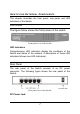
IDENTIFYING EXTERNAL COMPONENTS This chapter describes the front panel, rear panel and LED indicators of the Switch Front Panel The figure below shows the front panels of the switch. Front panel view of the Switch LED Indicators Comprehensive LED indicators display the conditions of the Switch and status of the network. A description of these LED indicators follows (see LED Indicators). Rear Panel The rear panel of the Switch consists of an DC power connector.
Power is supplied through an external AC power adapter. Check the technical specification section for information about the AC power input voltage. 1000BASE-T Ports: Five Gigabit Ethernet Negotiation interface. ports of 10/100/1000Mbps Auto- LED Indicators The LED indicators of the Switch include Power, Link/Act, 1000Mbps and 100Mbps. The following shows the LED indicators for the Switch along with an explanation of each indicator.
TECHNICAL SPECIFICATIONS General Standards: IEEE 802.3ab 1000BASE-T IEEE 802.3u 100BASE-TX IEEE 802.3 10BASE-T IEEE 802.3x Flow Control Protocol: CSMA/CD Data Transfer Rate: Ethernet: Fast Ethernet: Gigabit Ethernet: 10Mbps (Half-duplex) 20Mbps (Full-duplex) 100Mbps (Half-duplex) 200Mbps (Full-duplex) 2000Mbps (Full-duplex) Topology: Star Network Cables: Ethernet: 2-pair UTP Cat. 3,4,5, Unshield Twisted Pair (UTP )Cable Fast Ethernet: 2-pair UTP Cat.
Physical and Environmental DC inputs: Power Consumption: Operating Temperature: Storage Temperature: Humidity: Dimensions: Certification: 7.
Note: In the event of incorrect installation and improper use in a residential area, the device may cause disruptions in radio devices and other electronic devices. Proper use means that the device is operated with shielded connector cables as far as possible, for network products also with shielded cables of category 5e and higher. The device was tested and lies within the limits for computer accessories of class A according to the requirements of EN 55022. Warning ! This is a class A device.