TE800 Series TE820B / TE820 User Manual 601-00019 Rev.
Digium, Inc. 445 Jan Davis Drive NW Huntsville, AL 35806 United States Main Number: 1.256.428.6000 Tech Support: 1.256.428.6161 U.S. Toll Free: 1.877.344.4861 Sales: 1.256.428.6262 www.digium.com www.asterisk.org www.asterisknow.org © Digium, Inc. 2013 All rights reserved. No part of this publication may be copied, distributed, transmitted, transcribed, stored in a retrieval system, or translated into any human or computer language without the prior written permission of Digium, Inc. Digium, Inc.
Compliance Information Compliance information for this product is available at http://www.digium.com/ccs-compliance. Digium, Inc.
Introduction to TE800 Series Documentation This manual is a user guide for Digium’s TE800 Series cards. The Digium TE800 Series cards are a T1/E1 capable card series created for voice. The cards in this series are as follows: Table 1: TE800 Series Cards Model TE820B TE820 Digium, Inc.
Document Organization The TE800 Series user’s guide is organized in the following manner: Chapter/ Appendix Title Description 1 Overview Identifies the features of the card you received. This chapter covers applications and uses of the TE800 Series cards in the real world. 2 Card Installation Provides instructions for installing the card in your PC, acquiring correct drivers, and checking device compatibility. 3 Configuration Provides examples for configuring dial plan options.
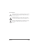
Symbol Definitions Caution statements indicate a condition where damage to the unit or its configuration could occur if operational procedures are not followed. To reduce the risk of damage or injury, follow all steps or procedures as instructed. The ESD symbol indicates electrostatic sensitive devices. Observe precautions for handling devices. Wear a properly grounded electrostatic discharge (ESD) wrist strap while handling the device.
Important Safety Instructions User Cautions Servicing. Do not attempt to service this card unless specifically instructed to do so. Do not attempt to remove the card from your equipment while power is present. Refer servicing to qualified service personnel. Water and Moisture. Do not spill liquids on this unit. Do not operate this equipment in a wet environment. Heat.
TABLE OF CONTENTS Chapter 1 Overview . . . . . . . . . . . . . . . . . . . . . . . . . . . . . . . . . . . . . . . . . . . . . . . 12 Echo-Cancellation . . . . . . . . . . . . . . . . . . . . . . . . . . . . . . . . . . . . . . 17 What is Asterisk®? . . . . . . . . . . . . . . . . . . . . . . . . . . . . . . . . . . . . . 18 Asterisk as a Phone Switch (PBX) . . . . . . . . . . . . . . . . . . . . . . . . . 18 Asterisk as a Gateway . . . . . . . . . . . . . . . . . . . . . . . . . . . . . . . . . .
Table Of Contents Configuring Card Features . . . . . . . . . . . . . . . . . . . . . . . . . . . . . . . 42 Configuring T1/E1 Lines . . . . . . . . . . . . . . . . . . . . . . . . . . . . . . . . .45 Testing Your Configuration . . . . . . . . . . . . . . . . . . . . . . . . . . . . . . . 53 Chapter 4 Troubleshooting . . . . . . . . . . . . . . . . . . . . . . . . . . . . . . . . . . . . . . . . . 54 Appendix A Pin Assignments . . . . . . . . . . . . . . . . . . . . . . . . . . . . . . . . . . . . . . . .
List of Figures Figure 1: Figure 2 : Figure 3 : Figure 4 : Figure 5 : Figure 6 : Figure 7 : Figure 8 : Figure 9 : Figure 10: Figure 11: Digium, Inc. Sample Legacy Phone Application . . . . . . . . . . . . . .14 Sample Channel Bank Application . . . . . . . . . . . . . .15 Sample IP Phone Application . . . . . . . . . . . . . . . . . . 16 TE820B . . . . . . . . . . . . . . . . . . . . . . . . . . . . . . . . . . . 23 TE820 . . . . . . . . . . . . . . . . . . . . . . . . . . . . . . . . . . . .
List of Tables Table 1: Table 1: Table A-1: Table A-2: Table A-3: Table B-4: Digium, Inc. TE800 Series Cards . . . . . . . . . . . . . . . . . . . . . . . 4 Card Identifiers . . . . . . . . . . . . . . . . . . . . . . . . . . . 37 TE800 Series RJ45 Telco Port Connector. . . . . . . . . 60 Dongle Split A RJ45 Telco Port Connector . . . . . . . . 61 Dongle Split B RJ45 Telco Port Connector . . . . . . . . 62 Maximum Power Consumption . . . . . . . . . . . . . . . . .
Chapter 1 Overview The Digium TE800 Series is a T1/E1/J1 capable card series created for voice. They support industry standard protocols, including Robbed Bit Signaling (also known as CAS or Channel Associated Signaling), CCS (Common Channel Signaling), E&M, and Primary Rate ISDN (PRI). They are also capable of DACSing channels from one span to another. The TE800 Series cards are ideal for connecting phones to a channel bank, connecting to T1/E1 switches, or connecting to a legacy PBX.
Chapter 1: Overview Voice Modes: PRI CPE and PRI NET – NI1 – NI2 – EuroISDN – 4ESS (AT&T) – 5ESS (Lucent) – DMS100 – Q.SIG E&M – Wink – Feature Group B – Feature Group D FXO and FXS – Ground Start – Loop Start – Loop Start with Disconnect Detect The TE800 Series cards can be used to connect your Asterisk machine to the PSTN world, your channel bank, or even another PBX. This is accomplished via a T1/E1 interface. The cards allow Asterisk software to Digium, Inc.
Chapter 1: Overview connect to your network, creating a professional telephony environment. Figure 2 shows an example of the card’s primary application. Figure 1: Sample Legacy Phone Application Digium, Inc.
Chapter 1: Overview Figure 2: Sample Channel Bank Application Digium, Inc.
Chapter 1: Overview Figure 3: Sample IP Phone Application Digium, Inc.
Chapter 1: Overview Echo-Cancellation Users connecting their TE800 Series cards to the PSTN or other devices are likely to be placing calls that will result, at some point, in an unbalanced 4-wire/2-wire hybrid. The result of this hybrid is the reflection of a near-end echo to the calling party. Elimination of this echo is the responsibility of echo cancellation. The TE800 Series cards, unless otherwise equipped, utilize Asterisk to perform software-based echo cancellation.
Chapter 1: Overview What is Asterisk®? Asterisk is the world’s leading open source telephony engine and tool kit. Offering flexibility unheard of in the world of proprietary communications, Asterisk empowers developers and integrators to create advanced communication solutions...for free. Asterisk is released as open source under the GNU General Public License (GPL), and it is available for download free of charge.
Chapter 1: Overview architecture allows it to convert between a wide range of communications protocols and media codecs. Asterisk as a Feature/Media Server Need an IVR? Asterisk’s got you covered. How about a conference bridge? Yep. It’s in there. What about an automated attendant? Asterisk does that too. How about a replacement for your aging legacy voicemail system? Can do. Unified messaging? No problem. Need a telephony interface for your web site? Okay.
Chapter 1: Overview Asterisk Everywhere Asterisk has become the basis for thousands of communications solutions. If you need to communicate, Asterisk is your answer. For more information on Asterisk, visit http://www.asterisk.org or http://www.digium.com. Digium, Inc.
Chapter 2 Card Installation This chapter provides the following information: Unpacking the Card on page 22 Shipment Inspection on page 22 Identifying Ports on page 23 T1/E1 Selection on page 26 Connecting Timing Cables on page 27 Slot Compatibility on page 30 Hardware Installation on page 32 Software Installation on page 34 Note: The TE800 Series card installation instructions are written so that they will apply to any card in the series.
Chapter 2: Card Installation Unpacking the Card When you unpack your card, carefully inspect it for any damage that may have occurred in shipment. If damage is suspected, file a claim with the carrier and contact your reseller from which the card was purchased, or contact Digium Technical Support (+1.256.428.6161). Keep the original shipping container to use for future shipment or proof of damage during shipment. Note: Only qualified service personnel should install the card.
Chapter 2: Card Installation Identifying Ports The TE800 Series cards consists of 4 RJ45 ports and eight status LEDs. The ports are used for connecting T1, E1, or J1 cables via Y-adapter dongles. Refer to Figure 4 on page 23 and Figure 5 on page 24 to locate the ports and status LEDs. Note: The TE800 Series cards can be used without Y-adapter dongles, but only spans 1 through 4 will be accessible.
Chapter 2: Card Installation Span Status LEDs Figure 5: TE820 Digium, Inc.
Chapter 2: Card Installation The Y-adapter dongles are provided for accessing all 8 spans on the TE800 Series cards. Refer to Figure 6 and Figure 7 to identify a dongle and its split end ports. Pin assignments are available starting on page 60. Figure 6: Y-adapter Dongle Split A Spans 1-4 Split B Spans 5-8 Figure 7: Dongle Split End Digium, Inc.
Chapter 2: Card Installation T1/E1 Selection The TE800 Series cards can be configured for either T1 or E1 mode. The T1/E1 mode may be specified in the drivers using either the default_linemode=t1 or default_linemode=e1 module parameter when the drivers are loaded. This will set the mode for all spans on the card. T1 Mode (Recommended Method) - Include the following in /etc/modprobe.d/dahdi.
Chapter 2: Card Installation Connecting Timing Cables The timing port allows up to three TE800 Series cards to share the same sync (timing) source from the T1 line provider, or provide a consistent sync source across multiple cards. This is a useful feature for fax modes and some voice applications to prevent corruption due to timing slips on the second, or third cards. To utilize this feature, daisy-chain the P3 connector between each card using the Digium 3-position, 10-pin timing cable.
Chapter 2: Card Installation Figure 8: Differential Timing Port Example Digium, Inc.
Chapter 2: Card Installation Figure 9: Legacy Timing Port Example Caution. Only qualified service personnel should continue with hardware installation and configuration of the TE800 Series card. Non-qualified personnel should not attempt to perform these functions themselves. Digium, Inc.
Chapter 2: Card Installation Slot Compatibility Check your motherboard to verify that a compatible slot is available for a TE800 Series card. To determine which slots you have on your motherboard, identify them by comparing them to those shown in Figure 10. Slot Number: 0: AGP Pro Slot 1: 64-bit 5.0 volt PCI Slot 2: 64-bit 3.3 volt PCI Slot 3: 32-bit 5.
Chapter 2: Card Installation The TE820/TE820B card is keyed for a PCI Express 1-lane (x1) slot and will work in any PCIe revision 1.0 compliant slot, including lane lengths x4, x8, and x16. This means that in the motherboard shown in Figure 10, the TE820/TE820B card will fit into Slots 4, 5, 6, or 7 (PCI Express), but cannot fit into any of the other slots. Digium, Inc.
Chapter 2: Card Installation Hardware Installation 1. Now that you are acquainted with the cards, power down your computer and unplug it from its power source. 2. Attach a static strap to your wrist and open the case. 3. Remove the bracket place holder and insert the card into a PCI Express slot. See Figure 11 for an example of card installation. Figure 11: Insert the Card 4. Replace the cover to your computer. 5. Plug all T1 or E1 equipment cables and dongles into the RJ45 ports as needed. Caution.
Chapter 2: Card Installation Caution. This unit must be connected only to the appropriate Telecommunications Network port (as approved for use in your specific country). Digium, Inc.
Chapter 2: Card Installation Software Installation Digium hardware requires drivers and libraries that are not integrated with the Linux kernel. Digium hardware is supported only under Linux. Digium recommends CentOS, Debian, Red Hat, and Ubuntu distributions of Linux. However, many other distributions are supported by Digium Technical Support. Digium’s software, including drivers and application software, may be obtained from Digium’s download server at: http://downloads.digium.
Chapter 2: Card Installation installed any of these, Digium recommends that you upgrade to the latest “-current” version of each. Note: DAHDI 2.6.0 or newer is required. If you are using the 1.4.x series of Asterisk, you will need Asterisk 1.4.22 or newer. Digium, Inc.
Chapter 2: Card Installation 1. After the machine has booted to Linux, log in and execute the following command to list the devices detected by the PCI bus: # lspci -nn | grep d161 Confirm that the output from lspci lists a device with Digium’s PCI vendor ID which is “d161”. The screen output should be similar to the following: 04:08.0 Communication controller [0780]: Digium, Inc. Device [d161:] (rev 02) Note: The output from lspci may or may not state “Unknown device”.
Chapter 2: Card Installation Table 1: Card Identifiers Model TE820B TE820 Identifier 1820 1820 A Digium TE800 Series (TE820B/TE820) card identifier should be listed. If a matching card identifier is not listed, then your machine is not PCI Express compatible, and the card will not work with your motherboard. 2. Download the latest version of libpri. Substitute the version of libpri for the X.X in the command line below. libpri is available for download from: http://downloads.digium.
Chapter 2: Card Installation command lines below. # # # # tar -zxvf libpri-X.X-current.tar.gz cd libpri-X.X.X/ make make install 4. Download the latest DAHDI drivers with tools. DAHDI 2.6.0 or newer is required. DAHDI is available for download from: http://downloads.digium.com/pub/telephony/dahdi-linux-complete # wget http://downloads.digium.com/pub/telephony/ dahdi-linux-complete/dahdi-linux-complete current.tar.gz 5.
Chapter 2: Card Installation Installing Asterisk If you wish to use Asterisk with your new hardware, you can follow the instructions below. 1. Download the latest release version of Asterisk, either 1.4.22 (or later), 1.6.0.1 (or later), or 1.8.0 (or later). Substitute the version of Asterisk for the X.X in the command below. Asterisk is available for download from: http://downloads.digium.com/pub/telephony/asterisk # wget http://downloads.digium.com/pub/telephony/ asterisk/asterisk-X.X-current.tar.gz 2.
Chapter 2: Card Installation 3. If this is the first Asterisk installation on this system, you should install the sample configuration files. To do this, run: # make samples Note: Running this command will overwrite, after making a backup copy, any older Asterisk configuration files that you have in the /etc/ asterisk directory. If your installation has failed, it may be because you are missing one or more of the build dependencies, the kernel headers, or the development tools.
Chapter 3 Configuration The TE800 Series cards have a variety of configuration options. This chapter provides configurations for PRI, channel bank, and E&M wink. These sample configurations are provided to assist you in familiarizing yourself with the flexibility of editing the configuration files to meet your specific needs. The list of possible configurations is too expansive to cover in this user manual. Digium, Inc.
Chapter 3: Configuration Configuring Card Features You will need to modify the chan_dahdi.conf file which is located in the /etc/asterisk directory in order to configure the essential features of your card. This file is the configuration layer between DAHDI and Asterisk. Switchtype: national: dms100: 4ess: 5ess: euroisdn: ni1: qsig: National ISDN 2 (default) Nortel DMS100 AT&T 4ESS Lucent 5ESS EuroISDN Old National ISDN 1 Q.SIG Echocancel: Echo Cancellation is enabled in chan_dahdi.
Chapter 3: Configuration Users of open source Asterisk-based echo cancelers also have the following options: echocancel = 128 (this sets 128 taps or 16ms) or echocancel = 256 (this sets 256 taps or 32ms) Audio quality issues may result from choosing a taps length greater than the server's ability to process the echo in real-time. If audio quality is affected, reduce the taps length or combine your TE800 Series card with Digium's VPMOCT256.
Chapter 3: Configuration Signalling: pri_cpe for CPE side pri_net for NET side If you have a T1 PRI, add these lines to the following lines of the sample file.
Chapter 3: Configuration Configuring T1/E1 Lines 1. Begin by opening the system.conf file from the /etc/dahdi directory. 2. Specify the two letter country code for your loadzone and defaultzone. This will preload tone zone data and specify a default tone zone for your interfaces. The following is a typical setup for a telco in the US: loadzone = us defaultzone = us 3. Configure the SPAN Map. For each T1/E1 you are using, you will need to define a span.
Chapter 3: Configuration Timing: This determines how timing is handled by the card. 0 - This span is not used to determine timing. If all spans on the card are set to 0, the card will use its internal clock as the timing source. 1, 2, 3, ... - A value greater than 0 will cause the span to attempt to recover a clock source from the line for the entire card to use as timing.
Chapter 3: Configuration Coding: T1 coding can be AMI or B8ZS. E1 coding can be AMI or HDB3. E1 can also have the extra flag CRC4 at the end for CRC4 checking. Yellow: The optional yellow flag can be added at the end for transmitting a yellow alarm when no channels are open. The following is a typical setup for a telco in the US: span => 1,1,0,esf,b8zs In Europe: span => 1,1,0,ccs,hdb3 4. Specify the channel definitions.
Chapter 3: Configuration any channel. So, it is very important that you specify one in the system.conf file if you do not have hardware echo cancellers and need echo cancellation. The format is: echocanceller = , A list of valid echo cancellers are specified in the sample system.conf file. The following is a typical setup for a T1 PRI in the US using softwarebased echo cancellation: echocanceller = mg2,1-23 Digium, Inc.
Chapter 3: Configuration First Example: Channel Bank The Channel Bank in this example has 24 FXS ports. In this configuration, the system.conf is set for the card to provide timing to the channel bank and fxoks is set for 24 stations. Set chan_dahdi.conf to mirror the configuration with signalling = fxo_ks and define it for channels 1-24. /etc/dahdi/system.conf: loadzone = us defaultzone = us span = 1,0,0,esf,b8zs fxoks = 1-24 echocanceller = mg2,1-24 /etc/asterisk/chan_dahdi.
Chapter 3: Configuration Second Example: E&M Line In the E&M Line configuration, the system.conf is set for the card to take timing from the telco on E&M with wink while chan_dahdi.conf mirrors the configuration. Feat_D is a type of E&M with wink that accepts DID, but there are many other E&M options; E&M_W, E&M, Feat_B, etc. /etc/dahdi/system.conf: loadzone = us defaultzone = us span = 1,1,0,esf,b8zs e&m = 1-24 echocanceller = mg2,1-24 /etc/asterisk/chan_dahdi.
Chapter 3: Configuration Third Example: PRI By configuring the card for a T1 PRI line in system.conf, you acquire 23 bearer (B) channels for voice on the first 23 channels, and 1 delta (D) channel for signalling information on the 24th channel. In the chan_dahdi.conf file, define pri_cpe as the signalling type to act as the client side. Define the switch type you are connecting to as national. You will then have 23 voice channels for Asterisk. PRI T1: /etc/dahdi/system.
Chapter 3: Configuration PRI E1: /etc/dahdi/system.conf: loadzone = es defaultzone = es span = 1,1,0,ccs,hdb3 bchan = 1-15,17-31 dchan = 16 echocanceller = mg2,1-15,17-31 /etc/asterisk/chan_dahdi.conf: group = 1 echocancel = yes signalling = pri_cpe switchtype = euroisdn context = incoming channel = 1-15,17-31 Digium, Inc.
Chapter 3: Configuration Testing Your Configuration 1. Load DAHDI drivers into the kernel using the modprobe utility. The appropriate driver for the TE800 Series cards is wct4xxp. Users in all countries except Australia should use the following modprobe command: # modprobe wct4xxp # dahdi_cfg -vv 2. Run dahdi_tool from the command line and see if the span turns green for each span you have connected. # dahdi_tool 3. Execute the following Asterisk command to see if the span came up successfully.
Chapter 4 Troubleshooting This chapter provides frequently asked questions as identified from Digium Technical Support and possible resolutions. Multiple resources are available to obtain more information about Asterisk and Digium products. These resources are listed on page 59. What do the Status LED colors indicate? Steady Green - Card is in-sync with the far end. Steady Yellow - Card is synchronizing or is receiving a red alarm from the far end.
Chapter 4: Troubleshooting 1. Check the method being used by attempting the following in your line context: _X.,1,NoOp(My DID matches as ${EXTEN}) 2. Then type reload in the Asterisk console and call in. You should see the DID come in on your T1/E1 line. My D Channel seems to go up and down. Check to be sure you have set your timing parameters correctly. Also, check the common causes of problems for a T1. See the Common Fixes for all cards, page 58. I have trouble dialing out.
Chapter 4: Troubleshooting I am having issues with my PRI. How can I see the messages coming across my D channel? Enter the following command: *CLI> PRI debug span X where X is the port from which you are connected. This command will show you the PRI messages coming across your D channel for that span. I am still having problems and the telco tells me it is my equipment. The first thing to do in this situation is to test your equipment. Plug in a loopback cable.
Chapter 4: Troubleshooting Or if you have an E1 span: span => 1,0,0,ccs,hdb3 clear = 1-31 4. Navigate to the tools/ directory in your DAHDI complete source directory and type: # make tests Followed by: # ./patlooptest The first argument in the patlooptest command is the channel number you want to test. You should always test the first channel of a span. The second argument is the duration in seconds to run the test. This runs a pattern looptest for x seconds.
Chapter 4: Troubleshooting How can I enable more features? To view all of the options available to add to your dial plan, type the following commands from within Asterisk: *CLI> core show applications *CLI> core show functions Digium also offers services to help configure and add features you might need. Contact Digium Technical Support (+1.256.428.6161) for more information. Common Fixes for all cards 1. Check to see if the X Window System (e.g. X.
Chapter 4: Troubleshooting Check the current mode using this command: hdparm -vi /dev/[IDE Device] Use this command to set the drives into UDMA2 mode: hdparm -d 1 -X udma2 -c 3 /dev/[IDE Device] If you are still having problems, contact your reseller from which the card was purchased, or Digium Technical Support (+1.256.428.6161). Where can I find answers to additional questions? There are several places to inquire for more information about Asterisk Digium products: 1. Digium Technical Support (+1.256.
Appendix A Pin Assignments All four ports on the TE800 Series card bracket are 8-pin RJ45 ports. The pin assignments are identified in Table A-1. Table A-1: TE800 Series RJ45 Telco Port Connector Pin 1 Pin 8 Digium, Inc.
Appendix A: Pin Assignments Table A-2: Dongle Split A RJ45 Telco Port Connector Pin 1 Pin 8 Digium, Inc.
Appendix A: Pin Assignments Table A-3: Dongle Split B RJ45 Telco Port Connector Pin 1 Pin 8 Digium, Inc.
Appendix B Specifications This appendix provides specifications, required environmental conditions, and maximum power consumption for the TE800 Series cards. Physical (All Cards). Size: Weight: 6.6” × 3.93” × 0.062” (16.8 x 10 x 0.16 cm) PCB size, does not include the PCI bracket 4.5 oz (127gm) - Without Echo Cancellation Module Interfaces. Local Loop Access: E1, T1, J1, PRI; RJ45 (TE820) - PCI-E X1, compliant with PCI-E X1 1.0 or greater. Environment.
Appendix B: Specifications Hardware and Software Requirements. Equivalent of Pentium dual-core 1.8GHz processor or better 2GB RAM Available PCI-E (TE820) Slot Table B-4: Maximum Power Consumption Model Digium, Inc. Power TE820B 8.6 Watts TE820 4 Watts VPMOCT256 4.
Appendix C Glossary and Acronyms ACD Automatic Call Distribution A technology that distributes incoming calls to a specific group of devices that are associated to agents. Asterisk's Queue application performs automatic call distribution. ANSI American National Standards Institute An organization which proposes and establishes standards for international communications. asynchronous Not synchronized; not timed to an outside clock source.
Appendix C Glossary and Acronyms bit The smallest element of information in a digital system. A bit can be either a zero or a one. bps bits per second A measurement of transmission speed across a data connection. BRI Basic Rate ISDN broadband Broadband transmission shares the bandwidth of a particular medium (copper or fiber optic) to integrate multiple signals. The channels take up different frequencies on the cable, integrating voice, data, and video over one line.
Appendix C Glossary and Acronyms Cat5E Category of Performance for wiring and cabling. Category 5 Enhanced wiring supports signal rates up to 100 MHz but adheres to stricter quality specifications. CLEC Competitive Local Exchange Carrier A term for telephone companies established after the Telecommunications Act of 1996 deregulated the LECs. CLECs compete with ILECs to offer local service. See also LEC and ILEC. CO Central Office The CO houses local switching equipment.
Appendix C Glossary and Acronyms DS0 Digital Signal, Level 0 A voice grade channel of 64 kbps. The worldwide standard speed for digitizing voice conversation using PCM (Pulse Code Modulation). DS1 Digital Signal, Level 1 1.544 Mbps in North America (T1) and Japan (J1) -up to 24 voice channels (DS0s), 2.048 Mbps in Europe (E1) - up to 32 voice channels (DS0s). DS1/T1/E1 lines are part of the PSTN. DS3 Digital Signal, Level 3 T3 in North America and Japan, E3 in Europe. Up to 672 voice channels (DS0s).
Appendix C Glossary and Acronyms full duplex Data transmission in two directions simultaneously. FXO Foreign Exchange Office Receives the ringing voltage from an FXS device. Outside lines are connected to FXO ports. FXS Foreign Exchange Station Initiates and sends ringing voltage. Phones are connected to FXS ports. G.711 A recommendation by the Telecommunication Standardization Sector (ITU-T) for an algorithm designed to transmit and receive mulaw PCM voice and A-law at a digital bit rate of 64 kbps.
Appendix C Glossary and Acronyms HDLC High-Level Data Link Control A bit-oriented synchronous data link layer protocol developed by the International Organization for Standardization (ISO). IAX Inter-Asterisk eXchange The native VoIP protocol used by Asterisk. It is an IETF standard used to enable VoIP connections between Asterisk servers, and between servers and clients that also use the IAX protocol. iLBC internet Low Bitrate Codec A free speech codec used for voice over IP.
Appendix C Glossary and Acronyms LED Light-emitting Diode Linux A robust, feature-packed open source operating system based on Unix that remains freely available on the internet. It boasts dependability and offers a wide range of compatibility with hardware and software. Asterisk is supported exclusively on Linux. loopback A state in which the transmit signal is reversed back as the receive signal, typically by a far end network element.
Appendix C Glossary and Acronyms PBX Private Branch Exchange A smaller version of a phone company’s large central switching office. Example: Asterisk. PCI peripheral component interconnect A standard bus used in most computers to connect peripheral devices. POP Point of Presence The physical connection point between a network and a telephone network. A POP is usually a network node serving as the equivalent of a CO to a network service provider or an interexchange carrier.
Appendix C Glossary and Acronyms PTMP Point-to-Multipoint A connection where data is broadcast between more than two endpoints. PTP Point-to-Point A connection restricted to two endpoints. PTT Post, Telegraph, and Telephone The government agencies in many countries that traditionally operated and monopolized the public postal, telegraph, and telephone services. QoS Quality of Service A set of quality requirements for telephone service.
Appendix C Glossary and Acronyms SIP Session Initiation Protocol An IETF standard for setting up sessions between one or more clients. It is currently the leading signaling protocol for Voice over IP, gradually replacing H.323. T1 A dedicated digital carrier facility which transmits up to 24 voice channels (DS0s) and transmits data at 1.544 Mbps. Commonly used to carry traffic to and from private business networks and ISPs.
Appendix C Glossary and Acronyms tip and ring The standard termination on the two conductors of a telephone circuit; named after the physical appearance of the contact areas on the jack plug. twisted pair Two copper wires commonly used for telephony and data communications. The wires are wrapped loosely around each other to minimize radio frequency interference or interference from other pairs in the same bundle.