Drum/Wheelchair Scale DWP-1000L (1000Lb/0.
Content CHAPTER 1 MAIN SPECIFICATION CHAPTER 2 INSTALLATION CHAPTER 3 INDICATOR 1
Chapter 1 Main Specification 1. Model: DWP-L SERIES Drum/Floor Scale 2. Accuracy: GradeⅢ, n=10000 3. Sample Rate: 10 times/second 4. Load cell sensitivity 1.5~3mV / V 5. Scale interval: 1/2/5/10/20/50 for option 6. Display: 6 bits LED, 8 state indicating signals 7. Power supply: AC100V~230V,50~60HZ 8. Operating temperature/humidity: 0~50℃; ≤90%RH 9. Transporting temperature: -20~60℃ Chapter 2 Installation 2.0 SCALE BASE SETUP a. Open the scale base box (Box 1) with a knife very carefully.
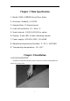
b. Take out the scale feet (total 4 feet packed in the box inside the scale base) c. Screw each foot ontothe load cell at each corner of the scale base.
d. Take out the indicator from Box 2. Plug the scale serial cable into the socket on the back of the indicator. And use a screw driver to tighten the two screws of the plug. Turn on the indicator by pressing the ON/OFF button on the front of the indicator. Now your scale is ready to use. For advanced operations, please refer to the following pages.
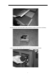
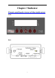
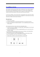
Chapter 3 Indicator Front and back view of the indicator Front: Back: 5
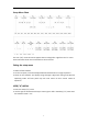
Connections Connection with Weigh Platform The indicators mounted in an ABS enclosure ship with a 15 ft shielded load cell cable for a connection to weigh platform’s load cell(s) or junction box. 1. Plug the cable’s 14-pin connector into the signal port on the rear panel of the indicator. Wire the bare wires and shield to the weigh platform’s load cell(s) or junction box using the color codes shown below: RED: BLACK: GREEN: YELLOW: +Excitation - Excitation +Signal - Signal 2. 2.
Configuration The indicator contains two main setup menus: The Setup (“H”) menu, which configures the indicator to your weigh platform and the User (“A”) menu, which configures the serial communication port and enables some user options. The Setup and User menus consist of several menu selections, each with its own sub-menu of choices. To set up the indicator, you must first enter the appropriate menu mode.
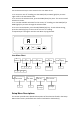
Setup Menu Chart The User (“A”) menu sub-menus appear when scrolling left or right from the “H” menu. Some selections shown are not available on some versions. Exiting the setup menu 1. Power off the indicator. 2. On the rear panel, move the Setup/Calibration Switch back to its original position. 3. Power on the indicator. The display will go through a digit check then go into Normal Operating mode. All front panel keys will now return to their normal mode of operation. USER (“A”) MENU 1.
Use the directional keys to move around in the User Menu Chart. 1. To move to a new “A” heading, use the TARE (left) or PRINT (right) key to move right or left in the User Menu Chart. 2. To move to the selection level, press the ZERO (down) key once. The current saved selection is shown. 3. To view the available selections for the current “A” heading, use the TARE (left) or PRINT(right) key to move through the selection field. 4. To save a new selection, press the NET/GROSS (Set) key .
NAME/CODE DESCRIPTION CODE/VALUE H1 Graduation Specifies number of full-scale graduations. Value should be consistent with legal requirements and environmental limits on the useful system resolution. 500 1,000 1,500 2,000 2,500 3,000 4,000 5,000√ 6,000 8,000 10,000 12,000 20,000 30,000 40,000 50,000 H3 Zero Track Band Selects the range within which the scale will automatically zero. Note that the scale must be in standstill to automatically zero. Selections are in Display Divisions. 0d 0.
NAME/CODE H9 Display Divisions DESCRIPTION Determines the desired weight increments. Value should be consistent with legal requirements. CODE/VALUE 1√ 2 3 H10 Decimal Pt. H15 Span Calib. Type 0 √ 0.00 0.0000 Selects the Span Calibration type. 1 -one time 1√ calib in the graduation. 2 - two times calib in the 2 graduation. 3 - three times calib in the 3 Determines location of the decimal point. 0.0 0.000 00 graduation.
User Menu Descriptions This section provides more detailed descriptions of the selections found in the User Menu Chart. Factory-set defaults are shown in bold with a checkmark (√).
NAME/CODE DESCRIPTION CODE/VALUE A1 Baud Rate Selects the baud rate for data transmission through the serial port. 1200 2400 4800 9600√ 19200 A2 Data Bits and Parity Selects the number of data bits and parity of serial transmission. "8n"=8 data bits with no parity bit and one stop bit. "7O"=7 data bits with odd parity bit and one stop bit. "7E"=7 data bits with even parity bit and one stop bit.
NAME/CODE DESCRIPTION CODE/VALUE A6 Serial Port Mode Select the mode of the RS-232 serial port; "0" = Full Duplex Mode "1" = Print Ticket Mode 0 A7 ID No. Enable Allows the ID number to be disabled in the Print Ticket mode. Valid only when A6 is set to "1". "0" = Disable the ID No. "1" = Enable the ID No. 0√ 1 A8 ID No. Entry Actuates the function that allows entry of a new ID No. 0-9999994 Valid only when A6 is set to "1".
Calibration The indicator is calibrated by following the procedures embedded in H16 (Zero) and H17 (Span) of the Setup Menu. Each procedure enters a value into the indicator's non-volatile memory -H16 the zero value (deadweight) and H17 the span value (test weight). The minimum test weight that can be used is 1% of full-scale capacity. After the two calibration procedures are executed successfully, you should record both calibration values in Table 6-1 using the H18 View procedure.
8. Repeat 2-4 using different test weight value and End C3 then revert to H17. 9. If the calibration was successful, revert to H17. 10. If the calibration was not successful, one of the error messages below will appear. Take the indicated action to correct the problem then perform a new calibration. "Err0" -The calibration test weight or the adjusted keyed-in weight is larger than the full capacity of the scale. Change the calibration test weight or check the input data.
Key-in span calibration value Note: This procedure is intended for emergency use only in the case of non-volatile memory loss. A valid span calibration value, obtained from a successful H17 calibration procedure, must be used. 1. While in the Setup mode, scroll to "H 20", then scroll down once using the ZERO key. 2. The display will momentarily show "CAL 1", followed by a flashing zero. Use the four directional keys (shown in Figure 6-1) to adjust the displayed value to the span calibration value. 3.
Operation Display Display Details Keyboard Units – This key toggles the indicator among the available weight units if enabled in the User (“A”) menu. Available weight units include lb and kg. Zero -This key sets the indicator to display zero provided the following conditions are met: 1 The indicator is displaying Gross weight. 2 The displayed weight is within the zero reset range that is programmed in H4 of the Setup (“H”) Menu. 3 The scale is not in motion or in overload.
Tare -This key is used to establish a Tare provided the following conditions are met: 1 The indicator is not at or below Gross zero. 2 The scale is not in motion or overload. Print -This key is used to send weight information out to the serial port provided the scale is not in motion or overload. Weighing 1 2 3 4 Select the desired weighing unit by pressing the lb/kg key until that unit is indicated on the display. If necessary, press the ZERO key to obtain a weight reading of zero.
Appendix A Error information: display mode description □□□□□□ weighing mode overload or without ADC input ERR0 H17 Span Calib. The calibration test weight or the adjusted keyed-in weight is larger than the full capacity of the scale. Change the calibration test weight or check the input data. ERR1 H17 Span Calib. The calibration test weight or the adjusted keyed-in weight is smaller than 1% of the full capacity of the scale. Change the calibration test weight or check the input data.