Dynaswitch & Cranegard User’s Manual
Table of Contents Section 1 Dynaswitch General Information ........................................................ 5 1-1 Introduction ............................................................................................ 5 1-2 General Description ............................................................................... 5 1-3 Safety ..................................................................................................... 5 1-4 Compression Models ......................................
Section 1: Dynaswitch General Information 1-1 Introduction The primary purpose of Model DS Dynaswitches® is to protect cranes, hoists and other lifting machinery against weight or force overload damages. They can also be used to perform control functions proportional to weight such as shutting down a pump when a tank is filled. As many as four standard microswitches can be installed on the Dillon Dynaswitch to perform multiple automated functions.
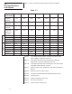
Table 1-1, below, contains key specifications and options available. 1-6 Key Specifications and Options Table 1-1 Basic Beam Part Number DSW-2 DSW-3 DSW-4 DSW-5 DSW-6 DSW-7 100 1000 2000 5000 10000 25000 50000 Minimum Set point* 15 100 200 500 1000 1250 2500 Repeatability pounds ±3 ±30 ±60 ±150 ±300 ±750 ±1500 0.02 0.03 0.05 0.05 0.05 0.06 0.06 Option A Avail. Avail. -- Avail. -- -- -- Option J Avail. Avail. -- Avail. -- -- -- Option B -- -- Avail.
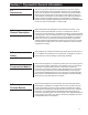
1-7 Microswitches Below are the four microswitches available and their specifications. Option A: 0.001” differential travel switch. Small size Dillon PN 26419-0026 (Cat. #11SM401-T.) S.P.D.T. 5 amps. resistive at 28VDC or 250VAC Option B: 0.002” differential travel switch Weatherproof Dillon PN 17891-0048 (Cat. #BZG1-2RN.) S.P.D.T. 15 amps. resistive at 125, 250 or 480VAC. ½ amp. at 125VDC. Option J: 0.004” differential travel switch Small size Weatherproof Dillon PN 26420-0015 (Cat. #1SE1.) S.P.D.T.
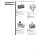
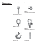
1-8 Attachment Fittings Attachment fittings for tension and compression models are shown below. Illustrations are not to scale.
Section 2 Installation 2-1 Mounting Positions Tension Models The best mounting position for a tension model is on the dead end of the line or on a crane anchor point. This mounting minimizes the effects of the machinery’s motion on the Dynaswitch. It keeps the switch in one relative position which reduces the possibility of wire tangling and connector damage.
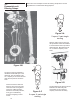
2-3 Dynaswitches & Reeving Setups Below are some examples of hoist and reeving setups which use the Dynaswitch for control and/or safety purposes. Figure 2-A 2 ropes, 2 part single reeving With two parts of line to the hook, the Dynaswitch should be installed in series between wire rope and its dead end point. Microswitch is set for ½ maximum capacity of the hoist. Figure 2-B As shown at right, Dynaswitch is installed in series with rope to the dead end.
2-4 Other Installation Possibilities Figure 2-E and 2-F show other uses for the Dynaswitch when either tension or compressions loads are present. Figure 2-E Batching operations at preset load points are greatly simplified by means of economical Dillon Dynaswitches. Figure 2-E shows a typical hopper with 3 point suspension. Dynaswitch under one suspension point is set for 1/3 maximum load. It opens hopper gate automatically at this point.
2-5 Dynaswitch Selection To pick the proper sized Dynaswitch for the job, do the following: 1. Determine the mounting position. 2. Calculate the load to be applied to the Dynaswitch. 3. Refer to Table 1-1 to select a Dynaswitch with the proper capacity and minimum/maximum set point range. 2-6 Dynaswitch Field Installation Procedures Loads applied to compression Dynaswitches cause the force beam legs to deflect and come closer together.
2-6-C Setting the Set Points 1. Figure the desired set point, in pounds, for each microswitch. In setting two, three or four switches, set the highest set point first, then work down according to weight. Any other sequence will cause a shutdown during the adjusting process. 2. Turn the adjustment screw: In compression models, back the adjustment screw as far as it will go away from the switch plunger.
Low Differential Travel Switch (For 100, 1,000 and 5,000 lb beams only) Circuitry Electrical Data UL Rating: 5 AMPS, 125 or 250VAC Single pole Double throw Weatherproof Low Differential Travel Switch (For 2,000, 10,000, 25,000 and 50,000 lb beams only) Circuitry Single pole Double throw Electrical Data UL Rating: L 74 15 AMPS, 125, 250 or 480 VAC; 2 AMPS, 600 VAC; 1/8 HP, 125 VAC; 1/4 HP, 250 VAC; .5 AMPS, 125 VDC; .25 AMP 250 VDC.
Section 3 Operation 3-1 Safety Shutdown Function DO NOT override the safety shutdown circuit. This can result in injury to workers and damage to equipment. 3-2 Decreasing Load Operation Ensure that the Dynaswitch triggers both the increasing and decreasing load function as planned. Stop the machinery and adjust the switch or setup if a problem exists. 3-3 Automation Operation Ensure the automated machinery setup is working properly.
4-3 Authorized Replacement A. Attachment Fittings - The customer is authorized to replace only shackle and pin attachment fittings at their facility. Customers desiring replacement of any other attachment fitting must return the Dynaswitch to Dillon or a factory authorized distributor for attachment fitting replacement. The reason for this is that all attachment fittings other than shackles and pins are pinned to the force beam after assembly. B.
Section 5 Cranegard® Load Limit Switch 5-1 Introduction The Dillon Cranegard Load Limit Switch is used to protect cranes and hoists against overloading where it is impossible or inconvenient to use a Dillon Dynaswitch. This unit can be applied to wire rope without cutting or removing the dead end from its existing mount. It may also be used on machinery such as elevators to provide a switch action at a given load.
Section 6 Installation 6-1 Mounting Positions The best mounting position for the Cranegard Load Limit Switch is adjacent to the wire rope dead end point. It also could be installed adjacent to the equalizer sheave where wire rope movement is small (a few inches). The amount of wire rope movement around the equalizer sheave should be measured by marking the wire rope, noting the amount of movement, and allowing enough clearance for such movement when mounting the Cranegard unit.
6-3 Cranegard Field Installation Procedures A. The Cranegard is designed to be mounted on a slack line. If line is not slack, methods should be employed to shunt load in the cable area where Cranegard will be installed. Often wire grips and portable winches are used to accomplish this. B. Position the Cranegard at the desired location on wire and loosely attch the clamp wit the included screws. Tighten the screws so that the cable is loosely gripped between the top and the bottom of the clamp.
6-4 Electrical Wiring Any time the Dynaswitch is removed from the machinery and reinstalled, you must check the switch operation. Failure to do so could result in inaccurate actuation as the calibration could change. Micro-switch(es) are S.P.D.T. and have three contacts. One is normally open, one normally closed, and one is common. Therefore they can make or break a circuit (start or stop an operation) at a specific set point(s).