EDxtreme Dynamometer and Crane Scale Optional Communicator User Instructions 29808-0011 Issue AE
© Avery Weigh-Tronix, LLC 2012 All rights reserved. No part of this publication may be reproduced, stored in an electronic retrieval system, or transmitted in any form or by any means, electronic, mechanical, photocopying, recording or otherwise without the prior written consent of the copyright owner, or as permitted by law or under license. Full acknowledgment of the source must be given. Avery Weigh-Tronix is a registered trade mark of the Avery Weigh-Tronix, LLC.
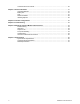
Table of Contents page Chapter 1 General information and warnings ......................................................................................... 5 About this manual .............................................................................................................. 5 Text conventions ......................................................................................................... 5 Special messages .................................................................................
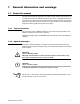
Communicator Print Formats ........................................................................................... 35 Chapter 7 General Information ............................................................................................................... 37 Changing Batteries .......................................................................................................... 37 Battery Life .......................................................................................................
1 General information and warnings 1.1 About this manual This manual is divided into chapters by the chapter number and the large text at the top of a page. Subsections are labeled as shown by the 1 and 1.1 headings shown above. The names of the chapter and the next subsection level appear at the top of alternating pages of the manual to remind you of where you are in the manual. The manual name and page numbers appear at the bottom of the pages. 1.1.
1.2 Safe Operation WARNING: If you overload this dynamometer you could suffer severe injuries or death. The total load on the dynamometer should NEVER exceed the rated capacity. Keep all the following in mind as you use the EDX dynamometer. The system capacity is equal to the rating of the dynamometers. The shackle rating should not be used to determine lift capacity of the system. The shackles are rated in metric tons.
l Environments with high electromagnetic fields such as cranes employing electromagnets to lift metal. These induce trace voltages that are picked up within the load cell lead wiring and appear as inaccurate loads. l Intrinsically safe environments. This unit has not been Factory Mutual tested. 1.2.1 Safe handling of equipment with batteries CAUTION: Danger of explosion if battery is incorrectly replaced. Replace only with the same or equivalent type recommended by the manufacturer.
To avoid the risk of RSI (Repetitive Strain Injury), place the machine on a surface which is ergonomically satisfactory to the user. Take frequent breaks during prolonged usage. 1.6 Sharp objects Do not use sharp objects such as screwdrivers or long fingernails to operate the keys. 1.7 FCC and EMC declarations of compliance 1.7.1 Modifications The FCC states that any changes or modifications to this device that are not expressly approved by Dillon may void the user’s authority to operate the equipment.
United States This equipment has been tested and found to comply with the limits for a Class A digital device, pursuant to Part 15 of the FCC Rules. These limits are designed to provide reasonable protection against harmful interference when the equipment is operated in a commercial environment. This equipment generates, uses, and can radiate radio frequency energy and, if not installed and used in accordance with the instruction manual, may cause harmful interference to radio communications.
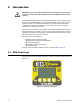
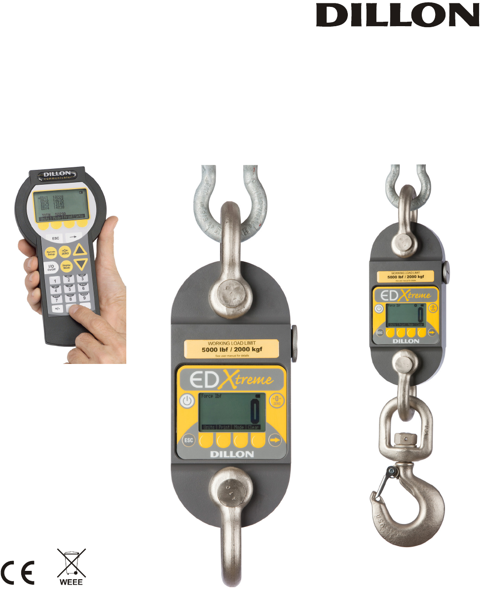
2 Introduction WARNING: If you overload this dynamometer you could suffer severe injuries or death. The total load on the dynamometer should NEVER exceed the rated capacity. The EDxtremeTM (EDX) electronic dynamometer from Dillon is a force measurement load sensor and digital readout in one instrument. The EDX can be used to measure tension or weight.
2.1.1 EDX Keys There are four “hard” keys and four “soft” keys. The hard keys are permanently labeled and the soft keys are just below the display. The soft key functions change and the key label appears above each key on the display. Sometimes the individual soft keys are referred to as the F1, F2, F3 and F4 keys as numbered from left to right. On/Off key Use this key to turn the unit on and off. ZERO key Use this key to zero the force indicated on the display.
2.1.3 Communicator Front Panel Figure 2.2 shows the Dillon Communicator. This is a battery powered, radio-linked (or wired) remote display and control unit. Figure 2.
2.1.4 Communicator Keys The Communicator has the same keys as the EDX but also some extra ones. They are all explained below: On/Off key Use this key to turn the unit on and off. Also, when in Radio Mode, this key will access a menu for further options. ZERO key Use this key to zero the force indicated on the EDX and Communicator displays. ESC key Use this key to escape from portions of the menu structure and return to previous choices or displays.
2.2 Power On and Annunciators When you power up the EDX you will see a display similar to the example shown on the left in Figure 2.3. Figure 2.3 Initial displays Depending on permission settings and/or revision of firmware, various soft keys may be in a different location or not visible. The display sample above shows several symbols you may see on your display but usually not all at the same time. Force. This tells you that the display is showing live force measurement at the moment.
Press the Arrow key, , to move between the two displays in Figure 2.3. In the display on the right in Figure 3, one of the soft keys is labeled Setup. Press this and you gain access to the soft keys shown in the Setup Menu in Figure 4.
3 EDX Operation 3.1 Display Modes The EDX has several display modes accessible by pressing the Mode soft key. See Figure 3.1. The first display mode when you power up is the live force measurement mode. Press the Mode soft key and the display changes to peak measurement mode. This mode shows the peak force applied to the EDX since the last peak clearing action. Delete the peak reading by pressing the Clear soft key. Power up display modes may be configured. See Config>Mode section.
3.3 Force Measurement Rezero Rezeroing allows the weight or load of fixturing to be invisible to the measurement. The zeroed load must always be considered as part of the maximum capacity. 1. Turn on the unit with the On/Off key. 2. Remove any weight from the EDX. 3. Zero the EDX by pressing the ZERO key. 4. Apply the tare force to the EDX and press the ZERO key. 5. Apply the force to the EDX and read the net force on the display.
4 EDX Setup To begin using the EDX, it is recommended that you set it up to suit your specific needs and equipment. You can access the SETUP menu with the soft keys. See Common Configurations on page 40 to view some common configurations. Figure 4.1 Operator setup menu for the EDxtreme See Figure 10 for communicator setup and corresponding flow diagram. 4.1 Setup Menu Press the appropriate soft key shown in Figure 4.1 to accomplish the functions listed on the following pages. 4.1.
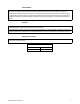
Format #1 Current displayed value (peak or live force) plus unit of measure 104.5 lbf (live force example) 302.5 lbf (peak force example) 104.5 lbf (dual mode example) 302.5 lbf Format #2 Live force value plus unit of measure on 1st line Peak force and unit of measure on 2nd line 104.5 lbf 302.5 lbf Format #3 Live force value plus unit of measure on 1st line Peak force and unit of measure on 2nd line Descriptive prefixes on each line Force 104.5 lbf Peak 302.5 lbf Format #4 Fixed position output.
Format #5 Live force, unit of measure, peak force, unit of measure. All tab separated. 104.5lbf (if presently displaying live readings) 302.5lbf (if presently displaying peak readings) 104.5lbf302.5lbf (if presently displaying dual mode) 4.1.2 Setup--Misc Press the Misc key to access the following soft key set (refer to Figure 4): Flash Press this soft key to enable or disable the “display flash” feedback.
4.1.3 Setup--About The next soft key is the About. The About menu shows an assortment of information about your Dillon instrument. This can be handy for maintaining calibration, troubleshooting or determining if the firmware can be upgraded. Press this and access the following soft key set (refer to Figure 4): Device Press this to see software revision and dynamometer information. Dillon suggests that calibration data be recorded and saved.
COM2 Press this key to test COM2 in a loopback test. To perform a COMM test, the unit must be configured to use RS-232 communications. It does not work in RS-485.
5 Configuration The configuration menu is a group of settings that may be password protected if desired to prevent operators from making significant system changes. It is used to configure the following: l l l l l l l l radio network resolution communication ports power up display mode units of measure power management password management system default reset To access the configuration menu, press the Config soft key shown in Figure 5.1. Figure 5.
5.1 Configuration Menu Figure 5.3 Configuration menu 5.1.1 Config--Setup The first soft key is Setup. Press this and you access the setup menu shown in Figure 4.1. All its features are covered in that section of the manual. 5.1.2 Config--Reso Reso stands for resolution. Resolution is the value by which the EDX displays increments. Press this key to set the unit to standard (1000 divisions) resolution or enhanced (5000 divisions) resolution.
5.1.3 Config--Comm Press the Comm key to enable or disable radio communication and configure serial ports. To configure serial ports, follow these steps: 1. Press the Comm key and you see the following screen: RS-232/RS-485 activity consumes more battery power. COM2 is used to configure the optional radio board, if installed. 2. Press COM 2 or COM 1. The following display appears. 3.
The following display appears: The * indicates which option is currently selected. The standard 4-pin connector only has one serial connection (COM 2). 4. Select a baud rate using the Sel keys to scroll through your choices. Choices are 1200, 2400, 4800, 9600, 19200, 38400, 57600 (default), and 115200. Press Enter to accept the setting.
5. Select a parity value using the Sel keys to scroll through your choices. Choices are none (default), odd and even. Press Enter to accept the setting. The following display appears: Default Serial Communications Baud Rate = 57600 Parity = None Databits = 8 Stop bits = 1 There is no option for handshakes. All settings should be None. 6. Select a databit value using the Sel keys to toggle between the two choices; 7 or 8 (default). Press Enter to accept the setting. The following display appears. 7.
If you enable the radio: l You are asked to enter a Radio Channel. Your EDX and Communicator must be on the same channel to function together. Key in a number from 1 through 64. 1 is the default setting. Press Enter to accept. l You are asked to enter a Network ID#. This is a unique address number (115) so the Communicator only speaks to one instrument at a time without “cross-talking.” Use the available soft keys to enter a number (1-15), then press Enter to accept.
3. To compensate for local gravitational differences. There are variances in gravity throughout the world. If used as a scale, variances due to gravitational differences can be handled by having the instrument calibrated on-site with certified dead weights or by using the custom units. Simply divide the gravitational constant at your location by 9.80665 m/ss (or 32.1741 ft/s2) and use this as the multiplier entry.
The following screen is displayed: Select Yes if you only want the instrument to automatically shut down when there is inactivity. Select No if you want the instrument to power down after the timer counts down, regardless of any activity. 5.1.7 Config--ChPwd The next soft key is ChPwd. Use this to change the password used to access the configuration menu. IMPORTANT: Changing the password denies access to this menu without entry of the new password.
6 Communicator Operation The Dillon Communicator is a remote display and control module designed to work with the EDxtreme. It can be connected by wire or can communicate by radio if both the Communicator and EDxtreme are equipped with optional radio boards. The Communicator may simultaneously view and control 15 dynamometers at one time. Each is monitored individually by assigning unique numeric identifiers (1-15) to each (addresses).
There are three soft keys on the first display and four on the second display. The soft key functions are described below: 6.2 Units Changes the displayed unit of measure. Each press advances the display through this sequence; lbf, kgf, N, custom 1, custom 2. Print Outputs serial data to peripheral devices attached to COM 1. C.All Clears the peaks on all EDXs currently in communication with the remote. Clear Clears the current peak value of the active EDX. UZ.
Next choice is number of EDXs in the network. Pick from 1-15 Next choice, you must set the address for each EDX. Each EDX in the network must have a unique number. Pick from 1-15. Misc Lets you setup the following items: Flash Use this to enable the visual confirmation of keystrokes. Display will flash on keystrokes if enabled. Zero Use this to enable or disable clearing of peak force values upon ZERO key press or Z.All soft key press. Contr Use this to adjust the contrast of the Communicator display.
Press ESC repeatedly to return to normal operation. If you have made changes you will be prompted to save the changes. Press the Save soft key to save the changes and return to normal operation. Press the noSave soft key to disregard any changes made and return to normal operation. Press the Cancel soft key to return to the Setup menu screen. This completes the Setup menu description. 6.3 Communicator Config Menu The configuration menu, shown in Figure 6.2, allows you to set the items described below.
Choice of power-up unit of measure Enable or disable lbf, kgf, N, custom unit 1 and 2 Power Press this to set the following: Enable Auto-shutdown (Y/N) Shutdown Timer (set minutes before idleness causes unit to shut off) 6.4 ChPwd Press this to change the Config menu password. Reset Press and you are given the choice of resetting the Communicator to its factory defaults.
Fixed characters. Position 1-8 Description Live force number 10-16 Displayed unit of measure (up to 7 characters) 18-25 Peak force number 27-33 Displayed unit of measure (up to 7 characters) 9,17,26 34 Commas Carriage Return Example 1: 104.5,lbf,302.5,lbf Example 2 (custom unit) 140000.,kg,165450.
7 General Information 7.1 Changing Batteries To replace discharged batteries, unscrew the battery compartment cap on the right side of the dynamometer. Remove the two C cells and replace them with the + poles inserted first. If the spring in the cap becomes detached, you can reattach it by aligning the large end over the counterbored hole and turning the spring counterclockwise while pushing the spring into the hole. The spring will work into the recess and be selfretained.
7.4 Radio Information The radio technology used in the radio equipped EDxtreme and Communicator is a 2.4 GHz digital spread spectrum system designed for communications reliability. Radio operation and the performance attained can be difficult to predict and will vary with environment and conditions. There are locations where radio use is impractical or even impossible. Tips for best performance: l l l Keep the Communicator and EDxtreme as close as possible together.
Place spacer on a solid surface and use a hammer to start the roll pins into the two small spacer holes. See Figure 7.2. Figure 7.2 Inserting roll pin Insert through matching holes in dynamometer body. Lay the dynamometer on the spacers on a solid surface with the roll pins protruding from the top. See Figure 7.3. Figure 7.3 Roll pins extending above dynamometer body Position the holes of the second spacer over the holes and tap spacer into position. See Figure 7.4. Figure 7.
8 Common Configurations EDxtreme being used stand-alone (no RS-232 or Communicator remote) Key Settings (EDxtreme): COM1 Trans Level – Disabled COM2 Trans Level – Disabled EDxtreme connected to a computer Key Settings (EDxtreme): COM1 Trans Level – Disabled COM2 Trans Level – RS-232 (all other parameters should agree with peripheral such as baud, data bits & parity) Communicator connected to one EDxtreme by wire on CELL port Key Settings (EDxtreme and Communicator): COM1 Trans Level – Disabled COM2 Trans L
Network Identifier: A Key Settings (EDxtreme 2): COM1 Trans Level – Disabled COM2 Trans Level – RF Radio Channel (1-64): 1 (must match Communicator channel setting) Network ID (1-15): 2 Network Identifier: B Key Settings (EDxtreme 3): COM1 Trans Level – Disabled COM2 Trans Level – RF Radio Channel (1-64):1 (must match Communicator channel setting) Network ID: 3 Network Identifier: C Key Settings (EDxtreme 4): COM1 Trans Level – Disabled COM2 Trans Level – RF Radio Channel (1-64):1 (must match Communicator c
9 Troubleshooting Problem Possible Cause Solution EDX powers on momentarily Low battery and turns off Bad keypad Replace with high quality alkaline batteries. Do not use rechargeable batteries. Have unit serviced. EDX does not power on Replace with high quality alkaline batteries. Do not use rechargeable batteries. Have unit serviced. Low battery Bad keypad Batteries installed backwards or no spring contact Insure that positive terminals of both batteries (nub) face inward – towards the black cap.
Problem Possible Cause Radio communications not working at all Dead batteries. Distance Bring remote closer to dynamometer. Allow several seconds to retrain. is excessive, dead radio pocket Radio systems not initialized. No “Y” appears. Displayed Solution Enable the radio system in the COM2 configuration of both instruments (under Comm menu). Change batteries in the device when the is blinking. Operating channels mis- Remote and link must be on the same operating channel.
10 Weighing and Force Measurement Practices The basis for all electronic force measurement or weighing is measurement of stress in a loadcell body. To obtain optimal results it is necessary to establish a few basic rules, otherwise the effect may be a nonlinear or non-repeatable response. Read and follow these tips and see the illustrations on the next page. 10.1 Load Centering For accurate performance the force acting on the unit must be in line with the unit.
10.
11 Specifications 11.1 Dynamometer Specifications Enclosure: Designed to NEMA4X/IP55. Suitable for continuous outdoor use. Accuracy: 0.1% of capacity.* 0.3% of capacity for EDX 75t and above* Repeatability: 0.1% of capacity. 0.3% of capacity for EDX 75t and above* *1 part in 1000 display mode with Dillon provided shackles. Factor of safety: 2.5K to 10K = 7:1 USF 25K to 100K = 5:1 USF, 220K to 330K 4:1 USF Body Protection: Powder painted aluminum or steel bodies.
11.2 Communicator Specifications Enclosure: Designed to NEMA 3 / IP44 with optional sleeve. Suitable for protected outdoor use. Instrument size: 9.0 x 4.6 x 1.8 inch (228 x 117 x 45mm). Accuracy: Not applicable. Only sends and receives digital information. Display: 128 x 64 dot-graphic LCD display can show full readings up to 5 instruments. Battery life: 60 hours wireline, 20 hours radio using four AA alkaline batteries under typical use.
EDxtreme User Instructions
Dillon A division of Weigh-Tronix Inc. 1000 Armstrong Dr. Fairmont, MN 56031 USA Telephone: 507-238-4461 Facsimile: 507-238-8258 e-mail: dillon@weigh-tronix.com www.dillon-force.