FI-80 LCD / FI-80 LED Indicators User’s Manual Contents subject to change without notice. Dillon division of Avery Weigh-Tronix 1000 Armstrong Drive Fairmont, MN 56031 USA Sales (507) 238-8796 Service (507) 238-4461 Register your Dillon product, get manuals and see other quality force measurement products at: www.dillonforce.
TABLE OF CONTENTS Page Introduction to the FI-80 Series Indicator........................................................................................ 3 Installation .......................................................................................................................................... 3 Operation ............................................................................................................................................ 4 Setup / Configuration............................
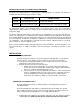
INTRODUCTION TO THE FI-80 SERIES DIGITAL INDICATORS The FI-80 Series Digital Indicator is a general purpose, industrial grade force indicator. Two models are available with different display types and power supply. MODEL DISPLAY TYPE FI-80 LED Light Emitting Diode (LED) FI-80 LCD Liquid Crystal Display (LCD) POWER SOURCE 110/220 VAC, 50/60 Hz Internal 6V battery with 12 VDC 800 ma charger The LCD model contains a 6V rechargeable battery as the primary power source.
matches the input voltage marked on the AC adapter. OPERATION DISPLAY The two display types are 6 digit LCD (Liquid Crystal Display) and 6-digit LED (Light Emitting Diode) display. Typically, LCD’s are used for outdoor applications while LED’s are used indoors where brightness is needed. Table 7-1 summarizes both types of display annunciators.
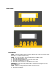
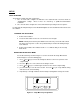
FRONT PANELS LED version front panel LCD version front panel FUNCTION KEYS PEAK – Toggles the indicator between normal live display mode and peak hold mode (Setup A5 must be set at “0” on the LCD version). ZERO - Sets the FI-80 to display “0” provided the following conditions are met: 1. The FI-80 is displaying Gross load. 2. The displayed load is within the zero reset range (F4 in setup). 3. The load is not in motion (F5 in setup). 4. The FI-80 is not in overload (see Appendix D for error codes).
3. The FI-80 is not in overload (see Appendix D for error codes). PRINT - Sends display reading through the serial port when the following conditions are met: 1. The display is not changing. 2. The FI-80 is not in overload (see Appendix D for error codes). See Appendix B for connection and print format details. UNITS – (LCD model only) Toggles the indicator between lb and kg if enabled (A5 at “1”) and peak hold is not configured (A11 at “0”).
1. All keys perform as described in the manual while in this mode. Peak-Hold Operation In Peak-Hold mode, the display updates as the load increases, but not as the load decreases. LCD version 1. Press PEAK to enter peak hold mode. The “P” annunciator appears on the left side of the display when PEAK HOLD mode is engaged and the value on screen is the peak value. 2. The ZERO key clears the previously stored peak value and zeroes the indicator.
SETUP SETUP OVERVIEW The indicator contains two main setup menus: 1. The “F” menu items configure the indicator to the attached load cell and is known as “Configuration” settings. Most of these are entered by a qualified instrumentation technician. 2. The “A” menu items configure the serial communication port and general user options. In setup mode the front panel keys become directional navigators to move around in the menus and to save the selections. ENTERING THE SETUP MENU 1. Power off the indicator.
EXITING THE SETUP MENU 1. Power off the indicator. 2. Move the slide switch on the rear cover back to the left. 3. Power on the indicator. The display will go through a digit check, then settle into Normal Operating mode. All front panel keys will now return to their normal mode of operation. SETUP MENU DESCRIPTIONS List and detailed descriptions of the items within the setup screens. Factory-set defaults are shown in bold with a checkmark (√).
F6 Digital Filter Averages load readings to produce higher stability. The higher the filter setting, the greater the stability but the slower the indicator’s response time. Choose 8 unless a very fast response is needed. 1 4 2 8√ FI-80 LCD extras: 16 32 64 128 F7 This item is for configuration by a qualified load cell indicator technician. Do not alter this value or the instrument may respond unpredictably.
A1 Baud Rate Baud rate for data transmission through the serial port. 1200 4800 19200 2400 9600√ A2 Data Bits and Parity Number of data bits and parity of serial transmission.
A11 (LCD version) Peak-Hold Mode Enables “Peak Hold” mode. The display will only increment upward and the peak reading is retained. Press PEAK key to enter and exit the mode once active. “0” = Peak Hold disabled, “3” = Peak Hold enabled 0√ 3 Note: UNITS are locked in default when A11 is enabled. A12 (LCD version) Handshaking Enables hardware handshaking for Print Ticket Mode. Valid only when A6 is set to “1”.
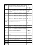
VIEW CALIBRATION VALUES (F18) 1. While in the Setup mode, scroll to "F 18", then scroll down once using the Calibration menu. key to enter View 2. The display will momentarily show "CAL 0" followed by a value. This value is the zero calibration value and should be recorded in the table below. Press any key to continue. 3. The display will momentarily show "CAL 1" followed by another value. This value is the span calibration value and should also be recorded in the table below.
APPENDIX A: SPECIFICATIONS ANALOG SPECIFICATIONS Excitation Voltage No load input Load cell output level Sensitivity Internal Resolution Display Resolution Measurement Rate System Linearity Calibration Method Maximum load cell support +10 VDC (LED), +5 VDC (LCD) 0.00 mV/V up to + 3 mV/V 0.4 μV / grad Approximately 150,000 counts 50,000 display division max 10 Measurements /sec, nominal Within 0.
APPENDIX B: SERIAL PORT INFORMATION B.1 SERIAL PORT MODES B.1.1 FULL DUPLEX MODE The Full Duplex Mode provides a Demand serial transmission mode and is selected by setting A3 to “d” and A6 to “0”. The Demand mode allows control from a host device, usually a PC, and can be activated by pressing the PRINT key on the indicator’s front panel. Figure B-1 shows a suggested cable diagram for interface to a PC. Figure B-2 shows the serial data format for the Demand Mode.
B.1.1.1 RECOGNIZED HOST COMMANDS “P” - This command is sent to the indicator to print the indicated display. The indicator will not respond if the scale is in motion, positive overload or negative overload. “Z” - This command is sent to the indicator to zero the scale. The indicator will not respond if the scale is in motion, positive overload or negative overload. The indicator will also not respond if it is not in gross mode or within the zero range specified in F4 of the Setup Menu.
B.1.3 SIMPLEX MODE The Simplex Mode provides a continuous serial transmission mode and is selected by setting A3 to “C” and A6 to “0”. The Continuous mode is used to interface to computers, scoreboards, and other remote devices requiring constant data updating. The transmission occurs at the end of each display update. Figure B-5 shows the serial data format for Continuous Mode. xxxxx.
APPENDIX C: DISPLAYED ERROR CODES CODE MEANING / POSSIBLE SOLUTION Gross Overload. A load greater than the rated capacity has been applied to the scale. Remove the load and verify operation. Contact your Dillon distributor with any problems. Err 0 Should not appear in normal operation. Contact your Dillon distributor. Err 1 Should not appear in normal operation. Contact your Dillon distributor. Err 2 Should not appear in normal operation. Contact your Dillon distributor.
This equipment has been tested and found to comply with the limits for a Class A digital device, pursuant to Part 15 of the FCC Rules. These limits are designed to provide reasonable protection against harmful interference when the equipment is operated in a commercial environment. This equipment generates, uses and can radiate radio frequency energy and, if not installed and used in accordance with the instructions manual, may cause harmful interference to radio communications.