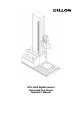
GTS-1000 Digital Control Motorized Test Stand Operator’s Manual
TABLE OF CONTENTS Introduction................................................................................................................................3 Safety and Equipment Precautions....................................................................................4 Set-up and First Configuration ............................................................................................6 Register ....................................................................................................
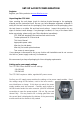
INTRODUCTION The motorized test stand is a tool to improve the quality of force testing results. It helps attain the best testing repeatability by pulling or pushing at extremely consistent speed in a direction in-line with the measuring device, such as a force gauge. Motorized stands also improve ergonomics and testing throughput. The Dillon GTS-1000 is a ball-screw driven digital test frame with capacity up to 1000 N (220 lbf / 100 kg).
SAFETY & EQUIPMENT PRECAUTIONS Read the instruction manual completely before attempting to use the GTS-1000 Test Stand. By following the instructions contained in this manual, the optimum accuracy and performance can be attained in the safest manner. RISK OF PERSONAL INJURY! Samples under test can store large amounts of energy which can be suddenly released upon sample failure. Sample failures can occur without warning.
crosshead traveling downwards and running fixtures together. minimize this situation. Take precaution to Verify alignment. Be sure to align any lower fixture location in line with the attached force gauge stem. The force must be applied in line for tests to be accurate and to avoid gauge damage. Understand all aspects of testing equipment operation before operating! See users manual or contact your Dillon dealer with any questions.
SET-UP & FIRST CONFIGURATION Register: Register your Dillon products at www.dillonforce.com. Unpacking the GTS-1000 Upon receiving the unit please check for obvious physical damage to the packaging material and the instrument itself. Be sure you have adequate equipment available to safely lift the test frame from the packaging. Once removed from the packaging, place the test frame on a stable, flat and level work surface. Inspect the machine for any signs of obvious transit damage.
CAUTION – Before connecting power: 1. Insure voltage setting on the stand agrees with your supply voltage. 2. Insure the AC power is regulated. Non-warrantable stand damage can result if not followed. If in question about your supply voltage or the stand voltage configuration, contact your Dillon distributor before connecting to power! Connect to power After all the above points have been checked and confirmed to be correct, connect your power cord and power the GTS-1000 on.
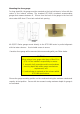
Mounting the force gauge For long stand life, the gauge must be mounted so the load cell stem is in-line with the center of the internal columns. The standard GTS-1000 crosshead accommodates gauges that measure between 8 – 28 mm from the back of the gauge to the load cell stem center AND have 57 mm twin vertical hole spacing. All GS/GTX Series gauges mount directly to the GTS-1000 tester in perfect alignment with the tester columns. Use included screws to secure.
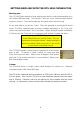
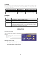
GETTING FAMILIAR WITH THE GTS-1000 CAPABILITIES Working area The GTS-1000 Series features a large working area ideal for testing large samples up to 10.2 inches (260 mm) wide. The versatile T-slots can secure unusual shaped fixtures or parts in tension. T-nuts and screws may be used to secure other fixturing. Do not allow fluid to run into the T-slots.
Crosshead The crosshead has six mounting holes for attaching a gauge with twin 2.25 inch (57 mm) hole spacing. The maximum stand capacity is dependent upon which position the force gauge is mounted to. Gauge mounting position Throat opening Maximum stand capacity A (closest to column) 2.64 inch / 67 mm 1000 N / 220 lbf / 100 kgf B (middle) 3.82 inch / 97 mm 750 N / 165 lbf / 75 kgf C (furthest from column) 5.
#1 Operating MODE The GTS-1000 has two operating modes, marked by an LED on the console. Press to cycle between: 1. Manual. Once UP or DOWN is depressed, the crosshead moves until any of the following occurs: a. Either MOVE key is pressed b. A limit switch is tripped (in the appropriate direction) c. The emergency stop button is pressed 2. Auto-reverse. This mode can speed up your repetitive batch testing.
The speed unit of measure is shown by an LED at right of window, either in/min or mm/min. To toggle between the units, press and keys at the same time. #3 MOVE Crosshead The GTS-1000 crosshead travel is controlled by the MOVE Keys. To begin the crosshead in an UPWARD direction, depress ×. To begin the crosshead in a DOWNWARD direction, depress Ø. The corresponding LED is lit while the stand is moving. The crosshead will not move in a given direction if it is against a limit switch stop.
- - Travel limits help protect your stand and force gauge from overloads by preventing fixturing from contacting when the crosshead is moving. Limits improve testing convenience by stopping at convenient test start and stop points. The crosshead will stop moving (or automatically reverse) when the crosshead comes in contact with a travel limit. You need to adjust these limits to your equipment and test to attain the benefits. To adjust, turn knob counterclockwise ½ to 1 turn.
PERFORMING A TEST Force of: a) b) c) d) e) f) g) h) i) j) k) l) testing is fairly easy and consistent with a little experience. It generally consists Attach the appropriate testing fixtures to the gauge. Attach the appropriate testing fixtures to the base. Ensure fixtures are in alignment. Position lower travel limit switch so fixtures cannot contact each other. Start software package such as Q-Graph or Q-Data. Secure your sample to the fixture on the gauge. Zero and reset the force gauge peaks.
TROUBLESHOOTING Behavior Problem Action No lights on front panel Power switch off Turn on power switch on rear of stand Power not connected Insure cord is secure at both ends and has supply power Power setting Verify supply power and power module setting Limit switch Attempt movement in other direction. Release limit switch. Emergency stop Release button.
Specifications Gauge mounting position Throat opening Maximum stand capacity A (closest to column) 2.64 inch / 67 mm 1000 N / 220 lbf / 100 kgf B (middle) 3.82 inch / 97 mm 750 N / 165 lbf / 75 kgf C (furthest from column) 5.00 inch / 127 mm 500 N / 110 lbf / 50 kgf Power consumption: 150 watts maximum Stand weight: 54 lb / 25kg Travel range: 18.7in / 475 mm Maximum headroom: 22.8 in / 580 mm Working area: 10.2 x 10.2 in / 255 x 255 mm Tension plate: Three 10-32 UNF holes Speed range: 0.2 – 40.