RL 1050 Instruction Manual Version 3.3 illon recision Products, Inc.
On the cover… The RL 1050 is pictured with optional accessories: Powdercheck System #21044 Low Powder Sensor #16306 Bullet Tray #22215 Other accessories available for the RL 1050 include: Machine Cover #13239 Maintenance Kit & Spare Parts Kit #97018 The Blue Press, Dillon’s monthly catalog, has a complete listing of accessories available for all machines. #13385 Spot Manuals RL1050 Man Folder RL1050 Manual V3.
Table of Contents Warranty Agreement 4 Mandatory Safety Measures 4 RL1050 Assembly 5 Powder Measure Adjustment 8 Primer Magazine 9 Electric Casefeeder 10 How the RL1050 Works – Stations 1 - 8 10 To Begin Reloading 11 Adjustments and Conversions: 11 Casefeeder 11 Handle 12 Swager 12 Swage Conversion & Adjustment 12 Primer System Change Over Instructions 12 Toolhead Removal 13 Shellplate Removal 14 Casefeed Plunger Conversion 14 Die Adjustments 14 Older Model Users 15 Tro
Dillon Precision Products, Inc. 8009 E. Dillon’s Way Scottsdale, AZ 85260 (480) 948-8009 FAX (480) 998-2786 Web Site: www.dillonprecision.com E-mail: dillon@dillonprecision.com Technical Support & Customer Service (800) 223-4570 Warranty Agreement Never operate the machine without ear and eye protection on. Call our customer service department at (800) 223-4570 for information on the wide variety of shooting/safety glasses and hearing protection that Dillon has to offer.
Seat bullets as close to maximum cartridge length as possible. Under some conditions, seating bullets excessively deep can raise pressures to unsafe levels. Refer to a reliable loading manual for overall length (OAL). • QUALITY CHECKS: Every 50-100 rounds, perform periodic quality control checks on the ammunition being produced. Check the amount of powder being dropped and primer supply. • RELOADING AREA: Keep your components safely stored.
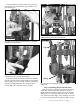
If you get stuck on something that you don’t understand, call (800) 223-4570 for technical assistance. Step 1: Mounting the RL1050 Select a clear area on your reloading bench. Be certain your bench is free from vibration and is strong enough to support your RL1050’s mass and operating force. If possible attach your bench to the wall using screws. Fig. 2: Locator button being inserted into its proper position. Install the six brass locator buttons (#20637*) around the shellplate (#12600*). Fig. 2 Fig.
The casefeed bowl assembly needs to be placed on the casefeed post with the Dillon logo and the on/off switch facing you. Fig. 6: See arrow. A slight gap allows the powder die to be adjusted without removing the powder measure. Fig. 4: The proper location and positioning of the casefeed tube and adapter is as shown above. Clip Fig. 5: The end of the casefeed tube marked “up” snaps into the clip at the base of the casefeeder motor housing.
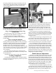
the spring (#14033) and wing nut (#13799) on the rod and screw the wing nut up until you feel light tension on the spring. Tighten the powder measure clamp screws (#14037). Fig. 9: This photo shows the powder bar at the end of its travel. It is important to understand that the adjustable powder bar should reach the end of its travel at the same time that the handle reaches the bottom of its stroke against the frame stop. Fig. 9 To achieve this adjustment, the die body must be screwed up or down as needed.
alternately raising and lowing the operating handle while adjusting the powder die. When properly adjusted, the powder bar will be moved to the end of its travel by the cartridge case Fig. 9. Collar Fig. 11: Clockwise turns of the powder bar adjustment bolt will increase the powder charge while counterclockwise turns will decrease the powder charge. You will notice an adjusting bolt on the front of the powder bar. Counterclockwise reduces the powder charge, clockwise increases the charge. Fig. 11 Fig.
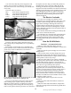
You will notice that the primer magazines and primer pick-up tubes have different colored tips. They have been color coded to help you identify size more easily. The color code is as follows: Blue Small Primer Magazine Orifice Red Large Primer Magazine Orifice Yellow Small Primer Pick-up Tube Green Large Primer Pick-up Tube the cap has a bevel to help you funnel the primers in. Hold the tube in place as shown in Fig. 14, pull the retaining pin and allow the primers to drop into the magazine.
As stated earlier, your dies have been adjusted at the factory. Before you change anything, try it the way it is, once you thoroughly understand the machine’s operation, make whatever adjustments to the dies you feel necessary. Reminder: There may be some variation due to components. should now be ejected into the collection bin. If all has gone well to this point you’ve got it made. Just keep adding bullets, watch your fingers so they don’t get caught and don’t hurry.
Begin by removing the swage cover (#13064). Next remove the hitch pin (#13840) and slide out the clevis pin (#13522). Rotate the swage connecting rod a half turn, this will allow you access to the swager. Pull the swager down and out of the machine. Insert the new swager and reassemble. Swage Adjustments 1/8” Use ONLY an unswaged military case for these adjustments. Fig. 16: Make sure the casefeed plate is centered in the bowl with approximately 1/8” all the way around when using the disc spacer.
Loosen the lever arm bracket screw (#13732) and slide the bracket assembly up four inches and lock it in place. Raise the operating handle, remove the two primer feed body screws (#13363) and lift the primer feed body assembly (#20773) off. Fig. 20: After removing the clip and disconnecting the rod, replace the clip in the rod for safe-keeping. Toolhead Removal Disconnect the mechanical return rod (#13960) from the bellcrank (#20319) by releasing the return rod clip (#13929). Fig.
When reinstalling the toolhead bolt (#13342) turn it in only finger tight then cycle the handle up and down to make sure everything is properly located. With the handle in the down position, tighten the toolhead bolt with the above mentioned wrench. Install the casefeed housing and insert the proper size adapter (#13654*). The casefeed tube (#13761) should now be inserted into the casefeed adapter (#13654*). Note that the tube is marked “up” on one end. Press this end into the tube clip (#13859).
Lower the platform and give the die an 1/8 turn down, again raise the platform. Lower the platform halfway and inspect the cartridge. If the bell is still present, or the desired amount of crimp has not been achieved, give the die a 1/8 turn down and try again. Continue making small adjustments to your crimp die until the desired amount of crimp has been achieved. Once the adjustment is complete, place the case back into Station 8 and raise the platform.
the swager up a quarter turn. Cycle the handle down. Raise the handle just enough to remove the case and inspect the primer pocket to see the amount of swaging being done. The swager should leave a radiused entrance on the primer pocket. Turn the swager in, using one quarter turn increments until you achieve the proper swage. Secure the jam nut (#13682). Note: Do not over swage. This condition will cause damage to the shellplate (#12600*).
c.) Check powder bar adjustment. 3.) Erratic belling: a.) Variation in case length. Divid cases by brand. b.) Handle not moving all the way down on each stroke. Note: Try setting a bullet on the case mouth in Station 6. 4.) Erratic powder charges: a.) Powder bar not moving full length of its travel. Turn the powder die down until it does. Station 7: Bullet Seating Problems 1.) Erratic seating depth of the bullet: a.) Build up of lead shaving and/or lube in the seater or crimp dies. b.
around the top of the primer pocket to prevent the primer from backing out. Usually found in military cartridges. Crimp must be removed to allow you to insert a new primer. DECAP: To push out a primer from the primer pocket with the decapping pin in the sizing die. EXPAND: To open rifle pistol cartridge casemouths to the proper diameter needed to hold the bullet firmly. Not to be confused with “belling”. FLARING: See BELL. FLASH HOLE: The hole leading from the primer pocket into the cartridge case.
Caliber Conversion Chart 20477 – .38/.357 Conversion 20482 – 9mm Conversion 20626 – .30 Carbine Conversion 12704 14062 13137 13802 13098 17384 13569 14067 13005 12938 14060 12833 13878 13306 17384 13569 14067 13005 12655 14048 12748 13564 12641 13306 17384 13569 14067 #2 Shellplate #2 Locator Buttons (6) .38/.357 cal.
RL 1050 Parts Listing Part # 11686 12144 12184 12260 12486 12819 12901 12930 12972 12995 13001 13042 13058 13064 13073 13086 13089 13091 13098 13108 13142 13161 13189 13205 13226 13238 13244 13245 13258 13262 13271 13276 13296 13306 13324 13328 13333 13335 13342 13363 13365 13376 13377 13392 13413 13417 13419 13426 13432 13435 13449 13475 13483 13484 13495 13498 13502 Description Toolhead Ratchet Cam 1050 Bullet Bin Bracket Swage Die Body – Part 1050 Box For Shipping Cam Guide Bolt 1/4x20 Primer System Pus
RL 1050 Upper Machine Assembly #20420 – Toolhead Assembly 13342 13005 - 13015 12819 13449 see caliber conversion chart on pg. 19 13342 ;; ;; 20420 13449 Crimp Seating Die Die 13957 20773 20320 Sizing Die Expander – see caliber conversion chart on pg. 19 14067 13482 14067 12486 20420 13896 13161 11686 13142 13572 13142 13895 13561 20311 assembly ;;;;;;; ;;;;;;; ;;;;;;; ;;;;;;; See page 23 for more detail.
RL 1050 Lower Machine Assembly See page 25 – Casefeed Frame Assembly 13244 13392 See Item A below See item #22216 below 12901 13392 13475 Lower Machine Assembly #22216 – Connecting Rod Assembly 13142 13258 Part # 12901 13244 13392 13475 Item A – Swage Rod Assembly 14517 #22216 – Connecting Rod Assembly Part # 13086 13142 13258 13365 22216 13086 13365 17084 Description Crankshaft 1050 Crank Retaining Ring Crankshaft Bearing Journal Key 1050 Description Index Roller Bolt 1050 Mainshaft 1050 Main
Primer System Assembly - #20488 Upper 13957 Lower 13840 13001 ;; ;; 13363 20488 13363 17604 13130 - large 13222 - small 14037 13423 12995 14990 13844 20317 - small 20318 - large 13746 13296 13936 13607 13413 13858 20773 12849 - large 13307 - small 13058 Lower Assembly 22030 - small 22031 - large Stock 12849 12995 13058 13130 13222 13296 13307 13363 13607 13858 20317 Description 1050 Primer Punch – Large Primer System Tappet Primer System Rocker Arm Primer Punch Bushing – Large Primer P
RL 1050 Casefeeder Assembly Stock # 12144 13205 13238 13271 13377 13400 13473 13484 13494 13495 13502 13539 13540 13655 13688 13756 13761 13779 13812 13859 13895 13954 14022 14023 14026 17808 20322 20324 20641 21079 Description Bullet Bin Bracket Post Bolts Cartridge Bin Bracket Post Stud Bin Bracket Mount Screw Casefeed Bowl 1050 Casefeed Motor – 4 RPM (Not Shown) 1050 Cartridge Bin Casefeed Funnel Lower Cord Clamp Clamp Retaining Screw Casefeed Cord Set Casefeed Motor Cover 5/16 Washer Casefeed Funnel Ba
RL 1050 Casefeed Sub Assemblies #22221 – Powder Measure Assembly 13644 13951 13921 13882 20780 13943 Item A – Casefeed Frame Assembly Adapter – see caliber conversion chart on pg. 18. 20062 Stock # Description 13333 Bolt (Locator Tab) 13498 Plunger Roller 13534 Adapter Housing 13567 Casefeed Plunger Spring 13815 Adapter Housing Screw 13972 3/16 Roll Pin 13815 13534 Casefeed Plunger – see caliber conversion chart on pg. 18.
NOTES
NOTES