
Manual


7
* Indicates a caliber specific part – see the caliber conversion
chart on page 19 for the caliber you are loading for.
The casefeed bowl assembly needs to be placed on
the casefeed post with the Dillon logo and the on/off
switch facing you.
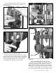
The casefeed tube (#13761) should now be inserted
into the casefeed adapter (#13654*) Fig. 4 Note that the
tube is marked “up” on one end. Press this end into the
tube clip (#13859) attached to the casefeeder motor
housing Fig. 5. This assembly is now complete.
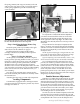
Step 3: Installing the Powder Measure
Remove the blue cap from the powder die (#20320)
and loosely clamp the powder measure in position.
Fig. 6 Install the powder measure return rod (#13960)
through the 3/8” eyebolt (#13089) mounted on the left
rear of the main frame. Fig. 7 Now attach the rod to the
powder measure bellcrank using the clip. Fig. 7 Install
Fig. 6: See arrow. A slight gap allows the powder die to be
adjusted without removing the powder measure.
Fig. 7: Note how the spring above the wingnut is slightly
compressed.
Clip
Spring
Fig. 4: The proper location and positioning of the casefeed tube
and adapter is as shown above.
Fig. 5: The end of the casefeed tube marked “up” snaps into the
clip at the base of the casefeeder motor housing.