
Instructions


Motor 1
with encoder
Limit
Switch
Normally
Closed
Motor 2
with encoder
Ground
Index
A
5 Volts
B
Ground
Index
A
5 Volts
B
|0V|5V|S1|S2|
M1A|M1B| B+ | B- |M2A|M2B
1 2 3 4 5 6
ON
Sabertooth
or SyRen
R/C Receiver
Limit
Switch
Normally
Closed
Limit
Switch
Normally
Closed
Limit
Switch
Normally
Closed
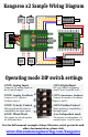
Kangaroo x2 Sample Wiring Diagram
1 OFF: Analog Input.
Connect 0-5V analog signals to
the S1 and S2 inputs.
1 ON: Digital Input
R/C to S1 and S2 or connect
serial TX to S1 and RX to S2
2 OFF: Analog Feedback
Connect a 0-5V signal to
Feedback Input A
2 ON: Quadrature Feedback
Connect an encoder to Feedback
Inputs A and B
3 OFF: Velocity Control
Motor speed and direction are
controlled by the input signal
3 ON: Position Control
Motor position is controlled by
the input signal
4 OFF: Mixed Mode
The outputs are mixed together
for differential drive
4 on: Independent mode
The outputs are independent. S1
controls motor 1 and S2 motor 2
Operating mode DIP switch settings
CH1 CH2
For the full manual, example videos, libraries, serial protocols and
other documentation, please visit
www.dimensionengineering.com/kangaroo