Kangaroo x2 Motion Controller March 2013 Kangaroo x2 adds feedback and motion control capabilities to Dimension Engineering’s SyRen and Sabertooth families of motor drivers. It is capable of reading one or two quadrature encoder or analog feedback sources and controlling one or two motors. It can be used to control position, speed, or both. Kangaroo can be commanded with analog signals, radio control, a microcontroller or a PC. Kangaroo x2 is self-tuning for ease of setup.
Table of Contents Position Control ............................................................................................................................................ 3 Speed Control ............................................................................................................................................... 4 Feedback .......................................................................................................................................................
Position Control If the Kangaroo is set up for position control, it will directly command the position of the output mechanism. Even if there is a load placed on the mechanism, the Kangaroo will apply as much power as is necessary to put or keep the device in the commanded position. By changing the commanded position, you can make the device move or stop in a controlled manner.
Speed Control If the Kangaroo is set up for speed control, it will command the device to move at a specific speed. Speed control works like the cruise control in a car: if the device encounters resistance such as going up a hill, it will apply more power to keep the speed to exactly the commanded speed. If it encounters less resistance than it is expecting, it will apply well power, or even apply braking, to keep the speed to what is commanded.
Feedback Kangaroo x2 requires a sensor telling the controller where the device is and how fast it is going. This sensor signal is called feedback. Kangaroo supports two different kinds of sensors, quadrature encoders and potentiometers. Quadrature Encoder Quadrature encoders are used to determine the position, speed and direction of a system.
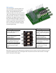
Kangaroo x2 Inputs and Connections Kangaroo x2 requires at minimum one signal input, one feedback input, one motor and must be connected to a Sabertooth or SyRen motor driver to operate. Feedback Input Kangaroo supports 5v optical, magnetic or mechanical quadrature encoders. Index pins may be used to make the homing and range more accurate if desired. Connections are to the GND, I, A, 5v and B pins in a single row .1” pitch pin header type connection.
Motion Range Kangaroo supports several ways of defining the tuning and travel range. These are limit switches, mechanical stops and teach range. Limit Switches Limit Switches are switches placed at the extreme ends of the device’s travel range. When the device moves to or past the limit switch, the switch is pressed. It is a good practice to set the limit switch up on the side of the mechanism rather than directly in front of it.
Teach Range Instead of having the kangaroo automatically determine the travel range, you can also teach it a range manually. To do this, during tuning you select Teach Tune (Mode 1) then move the mechanism from one end of its travel to the other. The Kangaroo will save this range. During the tune, the Kangaroo will move the system between the positions you have taught in order to calculate the tuning parameters.
DIP switches The main Kangaroo operating modes and options are set using a four position DIP switch. The individual switches have numbers printed on one side, and the word “ON” on the opposite side. For the purposes of this document, the switch is considered to be ON when the toggle is towards the word ON, and OFF when the toggle is towards the number. The switches use flush actuators, so a pen or similar tool is necessary to switch them. This prevents accidental changing of mode during operating.
Control Inputs The control inputs on a Kangaroo x2 are the screw terminals labeled 0V, 5V, S1 and S2. 0V is the logic ground for the device, and must be connected to the ground of the device generating the signal. 5V is a 5V output that can optionally be used to power the potentiometer, receiver, microcontroller or other device that is generating the signals. If the signaling device is selfpowering, it should be left unconnected. S1 and S2 are signal connections.
Radio Control Input In R/C mode, the output position or velocity is controlled by an incoming R/C signal. This could be used for cruise control, automatically going the same speed up or down hills, with varying load and resistance. It can also be used to create arbitrarily large R/C servos, proper steering or other applications. This is also an easy mode to use with microcontroller boards, because nearly all microcontroller modules from Basic Stamps to Arduinos can output an R/C servo formatted signal.
1, units 180 degrees = 5000 millivolt Simplified Serial Commands Kangaroo supports plain text TTL level simplified serial input. The default serial settings to use this mode are 9600 baud, 8N1. All commands follow the same format. Spaces are ignored and can be added for readability. All commands consist of a channel number, followed by a comma, the command and a newline (Enter key) Channel Number tells which motor to move Channel Number 1 2 D T Channel mode and result Motor 1 Motor 2 Drive channel.
Readback Commands are used to read the position, speed and status of the device. They respond back in plain text on the S2 input. Command getp gets getpi getsi getmax getmin Result Get position. Returns the channel number, followed by a comma, followed by a capital P if the move is completed or a lowercase p if the move is still going on, followed by the position in units (plain text) followed by a return and a newline Get speed.
Setup Commands are used to define and initialize the motion environment. They must be sent each time the Kangaroo is powered up if they are used. They do not respond back. Command start units home Result This command must be sent before any other commands to the axis. Commands sent before a start command will be ignored or return an error. This command is used to change the input from machine units (millivolts or encoder lines) to a user defined unit system.
Error Codes If the Kangaroo is unable to respond appropriately to a readback command, it will respond with an error code instead of the usual return. Error codes begin with either an uppercase or a lowercase letter e. Error Code E1 E2 e2 E3 E4 E5 E6 Result Not started. The channel has not been started, or the Kangaroo has lost power during operation Example 1,getpi\r\n Not homed.
Autotuning Kangaroo has a button labeled “Autotune” between the speed limit potentiometers. During autotuning, the motor and any devices attached to it will move. For best results, have a representative load applied to the mechanism before starting the tuning sequence. For example, if you are building a positioning stage that will support from 0 to 200 lb, a good test load for tuning purposes would be 100 lb. Ensure that the mechanisms are near the center of their range of motion before starting the tune.
Setting up the tune parameters In setup mode, the tune number will continue to blink, but dimmer and more rapidly. Depending on the tune mode, there may be specific things that must be done with the system and inputs at this stage. Mode 1: Teach Tune In teach tune mode, you must physically move the system to teach the kangaroo the acceptable travel range for tuning. The motors will not be powered at this point. Push each axis to one end of its travel range, then to the other end of its travel range.
Mode 4: Input Calibrate Mode Input Calibrate mode is not technically a tune. Instead, it is used to calibrate the input signals. This is used in R/C and analog mode. Before entering input calibrate mode, make sure your input signals are connected, your transmitter is powered on if using radio control, and the inputs at their desired neutral position. Once in the tune mode, move each input slowly all the way to one side, and then to the other. Return the inputs to the desired center.
After tuning After tuning, you must power the device off and back on to use the new tune. Kangaroo will start back up under control in the mode defined by the DIP switch settings. If the tune failed, you must still power the device off and back on. However, the settings will not be saved.
Installation Kangaroo x2 will work with any Dimension Engineering motor driver with screw terminal inputs. To mount the Kangaroo x2, insert the PCB tabs labeled 0V 5V S1 and S2 into the 0v 5v S1 S2 terminal block of the Sabertooth or SyRen instead of wires, then tighten the terminal block down on the PCB of the Kangaroo to make connection. Set the motor driver to packet serial mode at address 128 as shown. Channels 1 and 2 Kangaroo x2 can support one or two motor channels.
Cheat Sheet This is a copy of the instruction sheet that ships with the Kangaroo X2.
Quick Start Tutorial The following tutorial will set up a system with one motor, quadrature encoder feedback, radio control input and a Sabertooth 2x25 motor driver. This tutorial uses a Teach Tune with a bare motor. We recommend this tutorial for anyone unfamiliar with feedback controls, or new to the Kangaroo x2 motion controller. Step 1: Connect the Kangaroo x2 Motion Controller to the input screw terminal of the Sabertooth as shown. Tighten all four connections.
Step 3: Connect the motor and battery leads to the Sabertooth. For the purposes of this tutorial, connect the motor to M1A and M1B. Leave the Sabertooth unpowered for now. Step 4: Connect the motor’s quadrature encoder to the #1 Feedback Input, as shown. At a minimum, connect the Kangaroo’s GND, A, 5V and B pins to the corresponding pins on the encoder. If the encoder has an index channel, connect it to the I pin.
Step 6: Connect a servo type pigtail to the 0V, 5V and S1 screw terminals of the kangaroo, as shown. The receiver will be powered by the Sabertooth’s BEC in this configuration. Step 7: Connect an R/C receiver to the servo pigtail. Power up the corresponding transmitter, but leave in in neutral. Step 8: Secure the motor to your workbench or mount it in your robot. During the tuning. The motor will move back and forth. You want to make certain it is not going to roll off the bench while it does this.
Step 9: Power up the Sabertooth. The motor should not move. Press and hold the Autotune button for two seconds, until the LED begins to repeatedly blink one blink, then release. This is Teach Tune mode. To select this mode and enter Teach tune setup, click the Autotune button again. Step 10: Turn the motor shaft half a turn to the right (or more, if you want the output range to be larger), then half a turn to the left (or more). Finally, turn the motor back to the center.
Step 12: Make sure the transmitter is on. Reboot the system by removing power to the Sabertooth and waiting until all LEDs go out. Then power the sabertooth back up. Move the transmitter joystick. The motor should move with the transmitter joystick like a servo motor would. The kangaroo system is now tuned. The Kanaroo will remember the range you have set and the tuning parameters to keep the motor under control from this point onwards, even if you remove power.
Homing With a teach tune using a quadrature encoder, you must position the system at the startup position before powering it on. This is not necessary with analog feedback or if using one of the more advanced tune modes such as Limit Switch or Crash Limit tuning. To use these modes, as well as learn about other things the kangaroo can do, please see the full kangaroo manual.
Troubleshooting Some common problems and solutions. My system does not stop when doing a Mechanical If the stops can’t prevent the mechanism from Stop tune. The wheels slip instead. moving, you will need to use limit switches instead. My system moves REALLY fast in the middle of the The system is trying to figure out how fast it can teach tune cycle. go, so this is technically correct. However, using a smaller teach tune range will prevent it from moving so fast.