
User's Manual


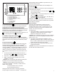


Table Of Contents

OPERATION
2
Proceed to the wiring instructions.6.
Supply Wiring and Heater Installation
WARNING:
be in accordance with the National Electric Code (NEC &
CEC) and local codes.
1.
2.
WARNING:
with the built-in thermostat.
.
3.
-4.
curing at the bottom using the supplied screw.
into place.
WARNING:
Figure 2
WARNING:
with the built-in thermostat.
.
CAUTION:
it is used.
!
NOTE: Prior to energizing remove all construction dirt
constant room temperature through the continuous addition
setting of the thermostat. The PCH operates such that once
will
continuously run
and the temperature of the heater will reduce so that the
temperature of the room will continue to be the same.
!
NOTE:
is a built in cool down period of 2 ½ minutes before the fan
WARNING:-
nect power to the heater and call a licensed electrician.
room.
!
NOTE: The unit is designed so that the fan and heater
be running at a low speed to maintain the room temperature.
Manual Controls
time either the ✚ or – button can be pressed to have the
A. Setting/Temperature Display
The PCH is designed to control the temperature of a room
✚ or –
will increase or decrease the desired temperature for the
!
NOTE: Pressing the ✚ and – at the same time will toggle
B. Comfort Setting
the room.
!
NOTE: Either the or
dependent on the setting being used.
M
L1
L2
R
G
Cutout
Over
Temperature
Light
Control
Board
Display
Board
Motor
Heater
Temperature
Sensor
Wiring