PARTS AND SERVICE MANUAL FOR THE 23” INSERT FIREPLACE MODEL NUMBER: HFPI9280 DFPI2311
TABLE OF CONTENTS OPERATION PAGE 1 PARTS DRAWING PAGE 5 PARTS LIST PAGE 6 WIRING SCHEMATICS PAGE 7 LIGHT BULB REPLACEMENT PAGE 8 MANUAL CONTROL ON/OFF SWITCH REPLACEMENT PAGE 9 FLAME MOTOR/FLAME ROD REPLACEMENT PAGE 10 POWER CORD REPLACEMENT PAGE 12 HEATER ASSEMBLY REPLACEMENT PAGE 13 REMOTE CONTROL CIRCUIT BOARD REPLACEMENT PAGE 14 HEATER DISABELER SWITCH REPLACEMENT PAGE 15
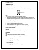
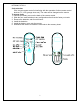
HFPI9280, DFI2311 OPERATION Initializing The Remote Control 1. Turn on the electrical power at the circuit breaker. 2. Slide open the battery cover on the back of the remote transmitter. 3. Install three AAA batteries into the remote control. Replace the battery cover. Note: The LCD display will flash when new batteries are inserted. 4. Move the remote transmitter close to the fireplace (less than five feet preferred). Press any button on the remote control.
HFPI9280, DFI2311 Auto Mode Note When auto mode is activated the flame and heat will turn on. The heater will turn on and off to keep the room temperature the same as the remote controls set temperature. 1. Use the UP and DOWN buttons to set the desired target temperature. 2. Press the AUTO/OFF button once to activate the auto mode.
HFPI9280, DFI2311 Code selection If the current remote control is interfering with the operation of other remote control devices (TV, VCR, garage doors etc.) The code can be changed on the remote. To change code: 1. Remove the battery cover on the back of the remote control. 2. Slide the four small switches to any configuration other than the factory set code. 3. Remove the batteries, wait for one minute. 4. Install the batteries. 5. Install the battery cover onto the remote. 6.
HFPI9280, DFPI2311 OPERATION Masonry Insert Manual Control 1. The masonry insert has a manual power ON/OFF switch located in the upper corner of the unit. 2. To operate press the switch once, to turn the unit on. A red light will illuminate to indicate the power is on. Press the switch again to turn the unit off. Note When the manual power switch is used the heater will run. The manual ON/OFF switch is to be used only when the remote transmitter is OFF.
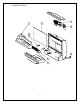
HFPI9280, DFPI2311 5
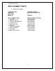
HFPI9280, DFPI2311 REPLACEMENT PARTS 23” FIREPLACE INSERT CATALOGUE NO. PART NO. MOD LEVEL: MADE IN: HFPI9280, DFPI2311 6900770259, 6900770159 A CANADA REPLACEMENT PART 1. LOG SET 2. FLICKER MOTOR 3. REFLECTOR ASSEMBY 4. LAMPHOLDER 5. BULB, 60W 120V 6. MIRROR 7. HEATER ASSEMBLY 8. CIRCUIT BOARD 9. CORD SET 10. REMOTE CONTROL REPLACEMENT PART NO.
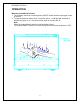
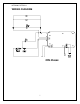
HFPI9280, DFPI2311 WIRING DIAGRAM 7
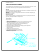
HFPI9280, DFPI2311 LIGHT BULB REPLACEMENT The light bulbs need to be replaced when you notice a dark section of the flame. There are two bulbs under the log set which generate the flames and embers. Warning Disconnect the power before attempting any maintenance or cleaning to reduce the risk of fire, electric shock or damage to persons. Warning Allow at least 10 minutes for the light bulbs and heater to cool before attempting any maintenance or cleaning.
HFPI9280, DFPI2311 If the unit was operating prior to servicing allow at least 10 minutes for light bulbs and heating element to cool off to avoid accidental burning of skin. Disconnect power before attempting any maintenance or cleaning to reduce the risk of electric shock or damage to persons. TO REPLACE MANUAL CONTROL ON/OFF SWITCH 1. Remove the glass doors and trim from the unit and remove it from the opening. 2.
HFPI9280, DFPI2311 If the unit was operating prior to servicing allow at least 10 minutes for light bulbs and heating element to cool off to avoid accidental burning of skin. Disconnect power before attempting any maintenance or cleaning to reduce the risk of electric shock or damage to persons. TO REPLACE FLAME MOTOR/FLAME ROD 1. Remove the glass doors and trim from the unit and remove it from the opening. 2. Unscrew the screws located in the middle of the top and the two screws at the back of the top. 3.
HFPI9280, DFPI2311 If the unit was operating prior to servicing allow at least 10 minutes for light bulbs and heating element to cool off to avoid accidental burning of skin. Disconnect power before attempting any maintenance or cleaning to reduce the risk of electric shock or damage to persons. TO REPLACE FLAME MOTOR/FLAME ROD 14. Install the flame motor strain relief grommet on the motor wiring and insert into the hole in the cover. 15. Reassemble in the reverse order as above.
HFPI9280, DFPI2311 If the unit was operating prior to servicing allow at least 10 minutes for light bulbs and heating element to cool off to avoid accidental burning of skin. Disconnect power before attempting any maintenance or cleaning to reduce the risk of electric shock or damage to persons. TO REPLACE POWER CORD 1. Remove the glass doors and trim from the unit and remove it from the opening. 2. Unscrew the screws located in the middle of the top and the two screws at the back of the top. 3.
HFPI9280, DFPI2311 If the unit was operating prior to servicing allow at least 10 minutes for light bulbs and heating element to cool off to avoid accidental burning of skin. Disconnect power before attempting any maintenance or cleaning to reduce the risk of electric shock or damage to persons. TO REPLACE THE HEATER ASSEMBLY 1. Remove the glass doors and trim from the unit and remove it from the opening. 2. Unscrew the screws located in the middle of the top and the two screws at the back of the top. 3.
HFPI9280, DFPI2311 If the unit was operating prior to servicing allow at least 10 minutes for light bulbs and heating element to cool off to avoid accidental burning of skin. Disconnect power before attempting any maintenance or cleaning to reduce the risk of electric shock or damage to persons. TO REPLACE THE REMOTE CONTROL CIRCUIT BOARD 1. Remove the glass doors and trim from the unit and remove it from the opening. 2.
HFPI9280, DFPI2311 If the unit was operating prior to servicing allow at least 10 minutes for light bulbs and heating element to cool off to avoid accidental burning of skin. Disconnect power before attempting any maintenance or cleaning to reduce the risk of electric shock or damage to persons. TO REPLACE THE HEATER DISABELER SWITCH 1. Remove the glass doors and trim from the unit and remove it from the opening. 2.