For service questions, please call Dimplex at 1-888-346-7539. For sales inquiries, please call Sylvane at 1-800-934-9194 or visit sylvane.com. Service Manual Model Number: DF2426 DF2550 DFG2562 BF9000 UL Part Number 6905050100 to 500 6907560100 IMPORTANT SAFETY INFORMATION: Always read this manual first before attempting to service this fireplace. For your safety, always comply with all warnings and safety instructions contained in this manual to prevent personal injury or property damage.
TABLE OF CONTENTS Operation. . . . . . . . . . . . . . . . . . . . . . . . . . . . . . . . . . . . . . . . . . . . . . . . . . . . . . . . . . . 3 Maintenance. . . . . . . . . . . . . . . . . . . . . . . . . . . . . . . . . . . . . . . . . . . . . . . . . . . . . . . . . 4 Exploded Parts Diagram: DF2426, DF2550, DFG2562, 6905050100-500 . . . . . . . .
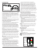
OPERATION Figure 1 C B A A. 3-Position Switch The switch has two On positions marked. The “ -- “ position is for manual operation. In this position the built-in remote control is by-passed. The “ = “ position is for operating the unit with the provided remote control. When in remote control (“ = “) position the unit is operated with the On and Off buttons of the remote control. When the switch is in the center “o” position the unit is off. B.
MAINTENANCE Light Bulb Replacement (Mod 0-A Only) Allow at least five (5) minutes for light bulbs to cool before touching bulbs to avoid accidental burning of skin. Light bulbs need to be replaced when you notice a dark section of the flame or when the clarity and detail of the log ember bed exterior disappears. There are two 2 bulbs under the log set, which generate the flames and embers.
EXPLODED PARTS DIAGRAM: DF2426, DF2550, DFG2562, 6905050100-500 MOD 0-A 9 3 5 11 14 13 1 16 16 4 7 8 15 6 10 12 Mod B 17 6 2 1. 2. 3. 4. 5. 6. 7. 8. 9. 10. 11. 12. 13. Remote Control. . . . . . . . . . . . . . . . . . . . 3000370500RP Flicker Motor. . . . . . . . . . . . . . . . . . . . . . 2000210200RP Heater Assembly (with cutout). . . . . . . . 2200491100RP Thermostat . . . . . . . . . . . . . . . . . . . . . . . 2300150100RP Cutout. . . . . . . . . . . . . . . . . . . . . . . . . . .
WIRING DIAGRAM: DF2426, DF2550, DFG2562, 6905050100-500 MOD 0-A MOD B THERMOSTAT OFF REMOTE HEATER ON/OFF MANUAL BLOWER HEATER ASSEMBLY FLICKER MOTOR ON/OFF REMOTE L SWITCH OUPUT N CAPACITOR CORD SET LED LIGHT HARNESS LED DRIVER BOARD 6 www.dimplex.
EXPLODED PARTS DIAGRAM - BF9000, 6907560100 MOD 0-A 17 3 9 4 5 1 14 7 13 8 16 6 15 11 10 12 2 MOD B 6 17 19 1. 2. 3. 4. 5. 6. 7. 8. 9. 10. Remote Control. . . . . . . . . . . . . . . . . . . 3000370500RP Flicker Motor. . . . . . . . . . . . . . . . . . . . . 2000210200RP Heater Assembly (with cutout). . . . . . . . 2200491100RP Thermostat . . . . . . . . . . . . . . . . . . . . . . 2300150100RP Cutout. . . . . . . . . . . . . . . . . . . . . . . . . .
WIRING DIAGRAM - BF9000, 6907560100 MOD 0-A OFF HEATER ON/OFF MANUAL THERMOSTAT REMOTE BLOWER HEATER ASSEMBLY FLICKER MOTOR ON/OFF REMOTE SWITCH OUPUT CORD SET CAPACITOR LIGHT HARNESS ASSEMBLY MOD B THERMOSTAT FLICKER MOTOR MANUAL OFF HEATER ON/OFF REMOTE BLOWER HEATER ASSEMBLY ON/OFF REMOTE L SWITCH OUPUT N LOG SET ASSEMBLY CORD SET CAPACITOR LED LIGHT HARNESS ASSEMBLY 8 www.dimplex.
PREPARATION FOR SERVICE CAUTION: If unit was operating prior to servicing allow at least 10 minutes for lights, heating elements and top panel to cool off to avoid accidental burning of skin. 1. Remove the firebox out of the cabinet or wall frame that surrounds the unit. 2. Disconnect power before attempting any maintenance. ! NOTE: This unit may have been installed to a power source in one of 2 ways: (SEE FIGURE 5 & 6). • Option #1 – Plugged into an outlet.
ing so that they will not be pinched when re-attaching the bottom panel. 14. Insert new bulbs. 15. Re-assemble the firebox in reverse order. ! NOTE: Ensure the rear tab/ledge on the log-set/emberbed is installed tightly under the bottom of the partially reflective glass to prevent light leakage. MOD B Tools required: Phillips head screw driver Small wire cutter CAUTION: Follow “Preparation for Service” instructions before proceeding. 1.
. Re-assemble the firebox in reverse order. ! NOTE: Ensure the rear tab/ledge on the log-set/ember-bed is installed tightly under the bottom of the partially reflective glass to prevent light leakage. HEATER ASSEMBLY REPLACEMENT Tools Required: Philips head screwdriver Needle nose pliers CAUTION: Follow “Preparation for Service” instructions before proceeding. 1.
provided with an insert connection, slide the plastic cover up and bend the connection in half. Remove the wire on the blower motor, that is running from the same spot off of the terminal block, install the new bent wire, then install the previously removed wire onto the bent connection. 7. Re-assemble in reverse order as described above.
them onto the same location on the new receiver board. ! NOTE: Using a flat head screwdriver gently pry between the end of the connector and the circuit board to release the wires. 6. Remove the old board off the plastic mounts, by squeezing the tab inward and sliding the board off. 7. Replace any plastic mounts that may have broken by pushing the old mounts out towards the back. Replace the new mounts from the back. 8.
ASSEMBLY PART PICTURES LOWER ELECTRICAL HOUSING VIEW FROM THE BOTTOM Flicker Motor Lower Terminal Block Flicker Motor Connection White (with capacitor wire) Capacitor - Connects to the terminals with the brown and white wires from the flicker motor Flicker Motor Connection White (with capacitor wire) Flicker Motor Connection - Black Single Light Harness Connection - Neutral Light Harness Connection - Live Power Cord or Hardwire Internal Connection Light Socket UPPER PANEL TERMINAL BLOCK CONNECTIONS
HEATER ASSEMBLY CONNECTIONS Blower Connects to Terminal Block White - Connects to Terminal Block White - Jumper to Blower Motor Jumper to “Piggy Back” connection on lower prong of element Yellow - Connects to Thermostat Grey - Connects to High Temperature Cutout on Terminal Block Red - From the high temperature cutout to the terminal block.
REMOTE CONTROL RECEIVER BOARD CONNECTIONS VIEW FROM THE TOP RIGHT SIDE Stand-Off Clips (4) - Attaching receiver board to housing Switch Output (Black) to outside prong of 3-Position Switch JP1 - Connects to inside prong of 3-Position Switch Switch Output (Black “Piggy Back”) to “Piggy Back” Connection on Outside Prong on Heater On/Off Switch JP3 (White) from upper terminal block JP3 (White “Piggy Back”) from lower electrical housing THERMOSTAT DIAL, HEATER AND 3-POSITION SWITCHES EXTERIOR VIEW OF SWITCH
TROUBLESHOOTING GUIDE PROBLEM CAUSE SOLUTION General Circuit breaker trips or fuse blows when unit is turned on Short in unit wiring. Trace wiring in unit. Improper circuit current rating Additional appliances may exceed the current rating of the circuit breaker or fuse. Plug unit into another outlet or install unit on a dedicated 15 amp circuit. Unit turns on or off by itself Remote Control has a similar frequency to other remotes in the area. Replace Remote Control.
PROBLEM CAUSE SOLUTION Heater Heater is not turning off Heater is not turning on Heater is turning off after a couple of minutes of operation Heater emits an odor Heater fan turns on but heater lacks heat Heating element is glowing red Heater fan runs continuously Improper operation Refer to Operation Section Defective Heater Switch Replace Heater Switch Defective Thermostat Replace Thermostat Defective Remote Control Receiver Replace Remote Control Receiver Improper operation Refer to Ope