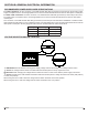
Installation Guide Model BF33STP/DXP BF39STP/DXP BF45DXP IMPORTANT SAFETY INFORMATION: Always read this manual first before attempting to install or use this fireplace. For your safety, always comply with all warnings and safety instructions contained in this manual to prevent personal injury or property damage. To view the full line of Dimplex products, please visit www.dimplex.
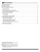
Table of Contents Listing and Code Approvals. . . . . . . . . . . . . . . . . . . . . . . . . . . . . . . . . . . . . . . . . . . . . . . . . . . . . . . . . . . . . . . . . . 3 Model Specifications. . . . . . . . . . . . . . . . . . . . . . . . . . . . . . . . . . . . . . . . . . . . . . . . . . . . . . . . . . . . . . . . . . . . . . . 3 Step-by-Step Installation . . . . . . . . . . . . . . . . . . . . . . . . . . . . . . . . . . . . . . . .
LISTING AND CODE APPROVALS The BF series fireplaces have been tested in accordance with the UL 2021 and CSA C22.2 No. 46 standards for fixed and location-dedicated electric room heaters.
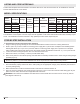
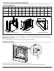
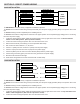
SECTION A: INSTALLATION INFORMATION FRAMING DIMENSIONS Model BF45DXP A B C D E F G H I J K L 16.0” 45.5” 33.5” 30.1” 15.3” 42.0” 44.7” 22.8” 32.7” 60.0” 42.0” 42.0” (40.5cm) (115.6cm) (85.1cm) (76.5cm) (38.9cm) (106.7cm) (113.5cm) (57.9cm) (83.1cm) (152.4cm) (106.7cm) (106.7cm) BF39STP/DXP 16.0” 39.5” 33.5” 30.1” 15.3” 36.0” (40.5cm) (100.3cm) (85.1cm) (76.5cm) (38.9cm) (91.4cm) 38.7” 22.8” 32.7” 54.0” (98.3cm) (57.9cm) (83.1cm) (137.2cm) 38.0” (96.5cm) 38.0” (96.5cm) BF33STP/DXP 15.
SECTION B: GENERAL ELECTRICAL INFORMATION RECOMMENDED POWER SUPPLY WIRE SPECIFICATIONS For 120V installations use two conductor, non-metallic sheath cable with ground wire (3 wires total) for the incoming power supply on fireplace inserts. Use the appropriate wire to meet local and national electrical codes for rated power consumption. For 208V / 240V installations use three conductor, non-metallic sheath cable with ground wire (4 wires total) for the incoming power supply on fireplace inserts.
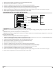
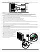
SECTION C: DIRECT POWER WIRING FIREPLACE JUNCTION BOX 240V INSTALLATION WHITE WIRE - N WHITE WIRE - N RED WIRE – L2 RED WIRE – L2 240 V POWER BLACK WIRE – L1 BLACK WIRE – L1 GREEN WIRE - G GROUND WIRE - G SUPPLY (BREAKER PANEL) ! IMPORTANT: The unit is factory configured for 208/240V operation. ! NOTE: Use 3 conductor wires with ground (4 wires total) from the power supply (breaker panel) to the junction box on the unit. ! NOTE: All wiring must be completed prior to installing the unit.
3. 4. 5. 6. 7. 8. 9. Remove the knockouts (if necessary) or use the provided cable clamp. Pull out the four wires marked L1, L2, N, and G. Connect L1 (black) wire from the unit to the L1 (black) from the power supply. Connect L2 (red) and N (white) from the unit to the Neutral (white) from the power supply. Connect the ground wire (green) from the unit to the ground from the power supply. When the unit has been configured for the appropriate power supply voltage, ensure that all connections are tight.
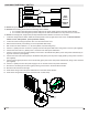
SECTION D: ALTERNATE CONTROL OPTIONS FIREPLACE JUNCTION BOX 240V MAIN POWER WALL SWITCH WHITE - N WHITE – N RED – L2 RED – L2 BLACK – L1 GROUND - G WALL SWITCH 240 V POWER BLACK – L1 SUPPLY GROUND - G (BREAKER PANEL) ! NOTE: This option should not be used with the remote control kit. ! NOTE: Before installing the unit have the following wires installed: ! 1. 2. 3. 4. 5. 6. 7. 8. 9. 10. 1. A 3 conductor wire with ground (4 wires total) from the power supply panel to the main switch wall box.
120V MAIN POWER WALL SWITCH FIREPLACE JUNCTION BOX WHITE - N WHITE – N RED – L2 120 V BLACK – L1 POWER WALL SWITCH GROUND - G BLACK – L1 SUPPLY GROUND - G (BREAKER PANEL) ! NOTE: This option should not be used with the remote control kit. ! NOTE: Before installing the unit have the following wires installed: ! 1. 2. 3. 4. 5. 6. 7. 8. 9. 10. 11. 12. 13. 14. 1. A 2 conductor wire with ground (3 wires total) from the power supply panel to the main switch wall box. 2.
120V MAIN POWER WALL SWITCH - NO HEAT WHITE - N FIREPLACE JUNCTION BOX WHITE – N RED – L2 BLACK – L1 120 V WALL SWITCH RED – 2 RED – 1 GROUND - G POWER SUPPLY BLACK – L1 (BREAKER PANEL) WIRE NUTS GROUND - G ! NOTE: This option should not be used with the remote control kit. ! NOTE: Before installing the unit have the following wires installed: ! 1. 2. 3. 4. 5. 6. 7. 8. 9. 10. 11. 12. 13. 14. 1.
FIREPLACE JUNCTION BOX 120V/240V HEATER WALL SWITCH CONTROL RED – 2 WALL SWITCH RED – 1 GROUND - G ! NOTE: Before installing the unit complete the following: ! 1. 2. 3. 4. 5. 6. 7. 8. 9. 10. 11. 12. 13. 1. Install main power connection with appropriate wiring - directly to the main power or through a wall switch. 2. Install a 2 conductor wire with ground (3 wires total) from the heater switch wall box to the junction box on the unit.
FIREPLACE JUNCTION BOX 120V/240V WALL MOUNTED THERMOSTAT RED – 2 WALL THERMOSTAT RED – 1 GROUND - G ! NOTE: Before installing the unit complete the following: ! ! 1. 2. 3. 4. 5. 6. 7. 8. 9. 10. 11. 12. 13. 1. Install main power connection with appropriate wiring - directly to the main power or through a wall switch. 2. Install a 2 conductor wire with ground (3 wires total) from the thermostat wall box to the junction box on the unit.
FIREPLACE JUNCTION BOX 120V/240V WALL MOUNTED FLAME OVERRIDE SWITCH BLUE – 4 WALL SWITCH BLUE – 3 GROUND - G DO NOT USE WITH NO HEAT INSTALLATIONS ! NOTE: The fireplace can be wired to have a wall switch operate the flame independent of the heater. ! NOTE: Before installing the unit complete the following: ! 1. 2. 3. 4. 5. 6. 7. 8. 9. 10. 11. 12. 13. 1. Install main power connection with appropriate wiring - directly to the main power or through a wall switch. 2.
WALL REMOTE - WRCPF-KIT 7 6 • • • • • • Can be used for 120V or 240V installations Battery or 24V powered 50’ (15m) control range Built in Thermostat Flame On/Off Control Heat On/Off Control 1 5 2 8 9 10 11 12 13 4 3 14 1. 2. 3. 4. 5. 6. 7. 8. 9. 10. 11. 12. 13. 14.