Service Manual Model BLF50 UL Part Number 6906780100 IMPORTANT SAFETY INFORMATION: Always read this manual first before attempting to service this fireplace. For your safety, always comply with all warnings and safety instructions contained in this manual to prevent personal injury or property damage. Dimplex North America Limited 1367 Industrial Road Cambridge ON Canada N1R 7G8 1-888-346-7539 www.dimplex.
TABLE OF CONTENTS OPERATION. . . . . . . . . . . . . . . . . . . . . . . . . . . . . . . . . . . . . . . . . . . . . . . . . . . . . . . . . 3 EXPLODED PARTS DIAGRAM . . . . . . . . . . . . . . . . . . . . . . . . . . . . . . . . . . . . . . . . . . 4 WIRING DIAGRAM. . . . . . . . . . . . . . . . . . . . . . . . . . . . . . . . . . . . . . . . . . . . . . . . . . . . 5 PREPARATION FOR SERVICE . . . . . . . . . . . . . . . . . . . . . . . . . . . . . . . . . . . . . . . . . .
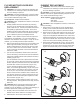
OPERATION Remote Control The BLF50 operates in a 3-Stage process. These stages can be controlled either by the remote control or by the manual controls which are located on the right side of the unit and inside the air intake slot (Figure 1). Figure 1 C B A The fireplace is supplied with a radio frequency remote control. This remote control has a range of approximately 50 feet (15.25 m), it does not have to be pointed at the fireplace and can pass through most obstacles (including walls).
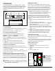
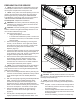
EXPLODED PARTS DIAGRAM 3 8 1 12 19 9 10 13 11 2 16 7 6 14 4 Replacement Parts List 1. 2. 3. 4. 5. 6. 7. 8. 9. 10. Element. . . . . . . . . . . . . . . . . . . . . . . . . . 2200510500RP Partially Reflective Glass . . . . . . . . . . . . 5901920100RP Blower/Fan. . . . . . . . . . . . . . . . . . . . . . . 5300260100RP Front Glass. . . . . . . . . . . . . . . . . . . . . . . 5901930100RP Power Cord. . . . . . . . . . . . . . . . . . . . . . . 8400320100RP Flicker Motor MOD 0-A . . . . . . . . . . . .
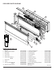
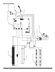
LED DISPLAY BOARD BLOWER CUT OUT ELEMENT LED DRIVER BOARD FLICKER MOTOR TERMINAL BLOCK CAPACITOR SWITCH BOARD WIRE NUT CORD 3-STAGE RECEIVER BOARD- LINEAR WIRE NUT SWITCH- ON/OFF WIRING DIAGRAM 5
PREPARATION FOR SERVICE Figure 3 Mounts (4) ! NOTE: All components are replaceable from the front of the fireplace while the unit is mounted on the wall, with the exception of replacement of the power cord. ! NOTE: If the power cord needs replacing or if the unit needs to be removed from the wall for any other reason please begin service by following the “PREPARATION FOR SERVICE” instructions, then move on to the section “INSTRUCTIONS FOR REMOVING FROM WALL”.
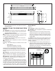
Figure 6 48 12 " (123 cm) 46" (116 cm) 3" (7.6 cm) 7" (17.8 cm) 50 5 16" (128 cm) 16" (40.6 cm) 19 12 (49.5 cm) 18" (45.7 cm) 3 13 16" (9.7 cm) 9. Proceed to the instructions within this manual relating to the repair being performed - see Table of Contents for page number. INSTRUCTIONS FOR REMOVING FROM WALL W ARNING: Disconnect power before attempting any maintenance or cleaning to reduce the risk of electric shock or damage to persons.
! NOTE: If the surface you are using as a work area on is a finished surface that is prone to scratches (i.e. hardwood flooring), it is recommended that a protective barrier be used underneath, (i.e. cloth, cardboard, thick plastic). 3. Proceed to the instructions within this manual relating to the repair being performed - see Table of Contents for page number. 4. Once repair is complete, reassemble in the reverse order as above.
to the repair being performed - see Table of Contents for page number. 5. Once repair is complete, reassemble in the reverse order as above. LED LIGHT STRIPS REPLACEMENT W ARNING: Disconnect power before attempting any maintenance or cleaning to reduce the risk of electric shock or damage to persons. CAUTION: If unit was operating prior to servicing allow at least 10 minutes for lights and heating elements to cool off to avoid accidental burning of skin.
FLICKER MOTOR/FLICKER ROD REPLACEMENT W ARNING: Disconnect power before attempting any maintenance or cleaning to reduce the risk of electric shock or damage to persons. CAUTION: If unit was operating prior to servicing allow at least 10 minutes for lights and heating elements to cool off to avoid accidental burning of skin. Tools required: Phillips head screwdriver. CAUTION: Follow “Preparation for Service” instructions before proceeding. 1.
farther down in the body of the unit, to give some room to access the heating assembly housing. 4. Release the top panel of the heating assembly housing by removing 4 screws on the side brackets. Pull the top panel of the heating assembly housing out from between the brackets. 5. From the top panel of the heating assembly housing, remove the 4 screws that hold the element cover to the housing panel. 6. Disconnect wires from the ends of the elements noting their original locations.
damage to the unit. 6. Disconnect the wiring connections noting their original locations. ! NOTE: Using a flat head screwdriver gently pry between the end of the connectors and the blower/fan to release the wires. 7. Properly orient the new blower/fan assembly and connect all of the wiring connections. 8. Reassemble in the reverse order as above. ON/OFF SWITCH REPLACEMENT W ARNING: Disconnect power before attempting any maintenance or cleaning to reduce the risk of electric shock or damage to persons.
1. On the top right side of the back panel, just below the manual control switches, remove the 2 screws that secure the upper control panel cover. Remove the cover and set aside to allow access to the Remote Control Receiver wires (the board is the larger circuit board on the left). 2. Remove any plastic cable ties to allow for easier removal of the wires on the Remote Control Receiver. 3. Remove the wires off the Remote Control Receiver, taking careful note of the original location of the wires.
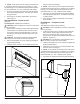
ASSEMBLY PART PICTURES 3-STAGE REMOTE CONTROL RECEIVER LED DRIVER BOARD MANUAL CONTROLS - Outside View REMOTE SWITCHBOARD - Inside View 14 www.dimplex.
LOWER ELECTRICAL HOUSING With Housing-Cover and Flicker Rod in place LOWER ELECTRICAL HOUSING With Housing-Cover and Flicker Rod Removed LED LIGHT STRIPS 15
LED LIGHT STRIP WIRE HARNESS HEATING ASSEMBLY ELEMENT CONNECTIONS Left and Right Side 16 www.dimplex.
HIGH TEMPERATURE CUTOUT Below Element Housing BLOWER MOTOR CONNECTIONS Below Element Housing 17
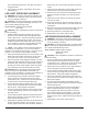
TROUBLESHOOTING GUIDE PROBLEM CAUSE SOLUTION General Circuit breaker trips or fuse blows when unit is turned on Short in unit wiring. Trace wiring in unit. Improper circuit current rating Additional appliances may exceed the current rating of the circuit breaker or fuse. Plug unit into another outlet or install unit on a dedicated 15 amp circuit. Unit turns on or off by itself Remote Control has a similar frequency to other remotes in the area. Replace Remote Control.
PROBLEM CAUSE SOLUTION Heater Heater is not turning off Heater is not turning on Heater is turning off after a couple of minutes of operation Heater emits an odor Heater fan turns on but heater lacks heat Heating element is glowing red Heater fan runs continuously Improper operation Refer to Operation Section Defective Remote Switchboard Replace Remote Switchboard Defective Remote Control Receiver Replace Remote Control Receiver Improper operation Refer to Operation Section Loose wiring Tra