
CFS30, CFS60, CFS90, CFS120 Fan Heater User Guide
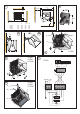


Wiring Diagrams
CFS30 - see Fig. 7.
CFS60, CFS90 & CFS120 - see Fig. 9.
A - Heat 1 Contactor
B - Heat 2 Contactor
C - Cut-out circuit
D - Mains In Terminal Block
E - Elements
T - Control Terminal Block
M - Motor
Switch Panel
Installation
The backing box should be fixed to a suitable wall with
appropriate conduit used where applicable to carry the cable
between the heater and the switch panel. (see Fig. 8 for
dimensions)
This cable used to connect the heater to the switch panel should
have sufficient cores (typically 5 core) to allow connection as per
the enclosed wiring diagram and be at least 1.0mm².
Test all switch settings once installation is complete.
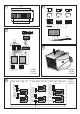
Switch Panel Connections
Connections are made as shown in Fig. 10. (References listed
below).
1 - FAN ON - OFF
2 - HEAT 1
3 - HEAT 2
T - TERMINAL BLOCK
SPC - SWITCH PANEL CABLE TO HEATER (NOT SUPPLIED)
Tip: When stripping back the switch panel cable make note of
the numbering or colours of each wire and their associated
connections to the terminal block.
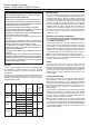
Operation of switch panel
Switch on electrical supply (MAINS IN) to the heater. Switching
the switch marked ‘I’ energises the fan. The heat selection
switches allow heat settings to be chosen as shown below:
Settings - I Fan Only
I +
Half Heat
I +
Full Heat
The desired heater setting can be obtained through switch
selection.
Thermal Safety Cut-out
The power supply to the heating elements will be interrupted if
one or a combination of the following abnormal events occurs:
1. Air inlet or outlet grilles are obstructed.
2. Internal ventilation is impaired due to build up of dust and
fluff.
3. Blower unit stalls.
NOTE: Before re-setting the reason for activation must be
determined and corrective action taken.
To reset the thermal safety cut-out for the CFS60, CFS90 or
CFS120 models, access reset buttons as shown in Fig. 11 and
push in direction of arrow. The CFS30 has an electrical reset
cut-out which requires the power supply to be removed for a
short period of time to allow the cut-out cool down. On return of
the power supply, the heater should operate normally.
Recycling
For electrical products sold within the
European Community.
At the end of the electrical products useful life it
should not be disposed of with household
waste. Please recycle where facilities exist.
Check with your Local Authority or retailer for
recycling advice in your country.
Cleaning
WARNING: DISCONNECT SUPPLY before carrying out
maintenance.
External appearance can be maintained by wiping occasionally
with a damp cloth. For stain removal, a weak soap solution can
be applied with a cloth and the surface wiped dry. Care must be
taken to avoid any moisture ingress into the product.
After Sales Service
Your product is guaranteed for one year from the date of purchase.
Within this period, we undertake to repair or exchange this product
free of charge provided it has been installed and operated in
accordance with these instructions.
Your rights under this guarantee are additional to your statutory
rights, which in turn are not affected by this guarantee.
Should you require after sales service you should contact our
customer services help desk on 0870 727 0101. It would assist
us if you can quote the model number, series, date of purchase,
and nature of the fault at the time of your call. The customer
services help desk will also be able to advise you should you
need to purchase any spares.
Please do not return a faulty product to us in the first instance as
this may result in loss or damage and delay in providing you with
a satisfactory service.
Please retain your receipt as proof of purchase.