PowerFlex® 700L TECHNICAL DATA LIQUID-COOLED ADJUSTABLE FREQUENCY AC DRIVES
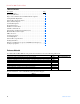
PowerFlex 700L Technical Data Table of Contents Description . . . . . . . . . . . . . . . . . . . . . . . . . . . . . . . . . . . . . . . . . . . . . Page Product Overview . . . . . . . . . . . . . . . . . . . . . . . . . . . . . . . . . . . . . . . . . . . 3 Key Features/Benefits . . . . . . . . . . . . . . . . . . . . . . . . . . . . . . . . . . . . . . . . 3 Easy to Use Communication and Human Interface Options. . . . . . . . . . . 4 Catalog Number Explanation . . . . . . . . . . . . . . . . . . . . . .
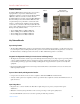
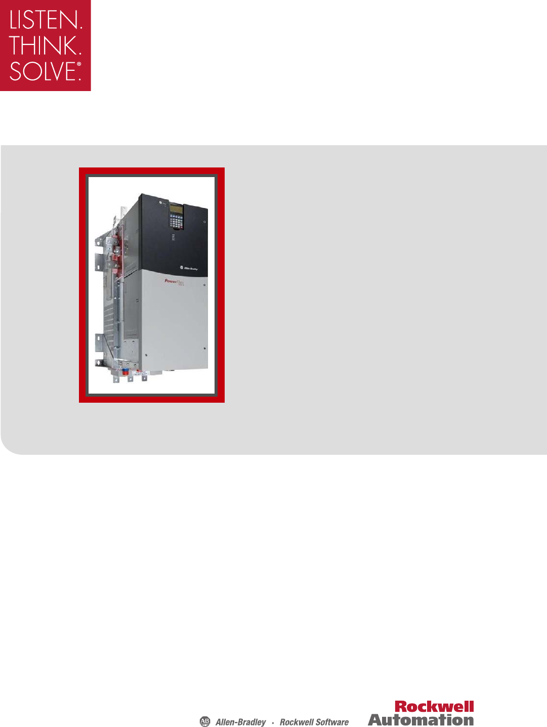
PowerFlex 700L Technical Data Product Overview Frame 2 PowerFlex 700L Liquid-Cooled AC drives are responsive, high performance, regenerative industrial drives for installations requiring a compact footprint. The PowerFlex 700L drive offers two versions of control: either the PowerFlex 700 Vector Control or the PowerFlex 700S Phase II Control.
PowerFlex 700L Technical Data Flexible Control Platforms • Designed for applications with requirements ranging from the simplest speed control to the most demanding torque control, the PowerFlex 700L drive is available with either PowerFlex 700 Vector Control or PowerFlex 700S Control. • Outstanding open or closed loop speed regulation for applications ranging from fans and pumps to precise winder control.
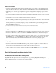
PowerFlex 700L Technical Data Communication Modules DPI communication modules provide fast and efficient control and/or data exchange over the following interfaces: • • • • • • DeviceNet™ ControlNet™ EtherNet/IP™ Remote I/O™ Serial Communications Other open control and communication networks Unsurpassed Capability in Network Communications Bluetooth® Siemens P1 FLN Metasys N2 Modbus TCP Modbus RTU LonWorks™ Interbus™ PROFIBUS DP RS485 DF1 Remote I/O EtherNet/IP™ ControlNet™ DeviceNet™ BACnet
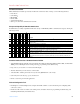
PowerFlex 700L Technical Data Catalog Number Explanation To interpret the meaning of a catalog number, match the values of the catalog number code in positions a, b, c, etc. with the tables labeled a, b, c, etc. below. Position 1-3 4 5-7 8 9 10 11 12 13 14 15 16 17 18 20L E 800 A 0 E N N A N 1 0 W A a b c d e f g h i j k l m n a d j Drive Enclosure Comm Slot Code Type 20L PowerFlex 700L b Voltage Rating Code Voltage Ph.
PowerFlex 700L Technical Data Position 1-3 4 5-7 8 9 10 11 12 13 14 15 16 17 18 20L E 800 A 0 E N N A N 1 0 W A a b c d e f g h i j k l m n k m Control Options Additional Config. Embedded Comm.
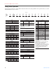
PowerFlex 700L Technical Data Standard Drive Product Selection 400V AC Three-Phase Drives Output Amps (with 400V AC Induction Motor) (1) Normal Duty Heavy Duty 110% 150% 150% 200% Cont. Cont. 1 Min. 3 sec. 1 Min. 3 sec. 360 396 540 264 396 540 650 715 975 475 715 975 1250 1375 1875 915 1375 1875 (1) (2) Nominal Power Ratings Normal Duty Heavy Duty kW 200 370 715 HP 268 500 960 kW 150 270 525 HP 200 365 700 IP20, NEMA/UL Type 1 (2) Catalog No.
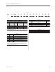
PowerFlex 700L Technical Data Factory Installed Options Feedback Options Human Interface and Wireless Interface Modules IP20, NEMA/UL Type 1 (Position e) Cat. Code Control Type Cat. Code: 3 LCD Display, Full Numeric Keypad Cat. Code: C Door Mounted Bezel LCD Display, Full Numeric Keypad NEMA/UL Type 1 0 All No Encoder 700VC 12V/5V Encoder 1 Resolver, 10…26V, 10 kHz, 10…16 bit A Stegmann - High Resolution Encoder Hyperface, 8.
PowerFlex 700L Technical Data User Installed Options Human Interface and Wireless Interface Modules No HIM (Blank Plate) 20-HIM-A0 LCD Display, Full Numeric Keypad 20-HIM-A3 LCD Display, Programmer Only 20-HIM-A5 Remote (Panel Mount) LCD Display, Full Numeric Keypad 20-HIM-C3S Remote (Panel Mount) LCD Display, Programmer Only 20-HIM-C5S Remote (Panel Mount) Wireless Interface Module 20-WIM-N4S Description Handheld/Local (Drive Mount) Remote (Panel Mount) IP66, NEMA/UL Type 4x/12 Cat. No. Cat.
PowerFlex 700L Technical Data Communication Option Kits Accessories Description Cat. No. ControlNet™ Communication Adapter (Coax) 20-COMM-C DeviceNet™ Communication Adapter 20-COMM-D EtherNet/IP™ Communication Adapter 20-COMM-E Note: Please refer to publication number 1756-TD008 for details on SynchLink. Description Cat. No.
PowerFlex 700L Technical Data Product Dimensions Frame 2 Drive Ground Terminal with 2 Clearance Holes for M8 Stud Dimensions are in millimeters and (inches). 389.6 (15.34) 351.0 (13.82) See DETAIL A 66.6 (2.62) 566.1 (22.29) 423.8 (16.68) POWER STS 153.8 (6.06) Motor W/T3 Output V/T2 Terminals U/T1 PORT MOD NET A NET B 591.2 (23.28) 3x Clearance Hole for M8 Stud 730.2 (28.75) 955.7 (37.63) 46.9 (1.
PowerFlex 700L Technical Data Frame 3A/3B Drive C 38 (1.50) INPUT FILTER BAY POWER MODULE BAY G Ø35 (Ø1.38) H Dimensions are in millimeters and (inches). 65 (2.56) 61 (2.39) J D Max. B E OUTLET INLET F Max. A Frame Size 3A 3B Dimensions A B C 1200 (47.2) 2000 (78.7) 600 (23.6) 1600 (63.0) 2200 (86.6) 800 (31.5) Publication 20L-TD001A D E F 2078 (81.9) 1500 (59.1) 233 (9.2) 2278 (89.8) 1500 (59.1) 233 (9.2) G 542 (21.3) 542 (21.3) H 542 (21.3) 942 (37.1) J 535 (21.1) 735 (28.
PowerFlex 700L Technical Data Installation Considerations Power Wiring The PowerFlex 700L has the following built in protective features to help simplify installation: • Ground fault protection during start up and running ensures reliable operation • Electronic motor overload protection increases motor life AC Supply Source Considerations PowerFlex 700L Liquid-Cooled AC drives are suitable for use on a circuit capable of delivering up to a maximum of 200,000 rms symmetrical amperes.
PowerFlex 700L Technical Data (Frame 2 Drive shown) POWER STS LCD Human Interface Module - Page 9 PORT MOD NET A NET B EMC Requirements - Page 14 Reflected Wave Reduction - Page 9 Cable Recommendations - Page 20 Integral Class 10 Motor Overload Removable MOV and Caps (underneath cover) - See PowerFlex 700L User Manual for locations and instructions Motor Recommendations See Publication MOTORS-CA001 EMC Requirements - See PowerFlex 700L User Manual Input Power Conditioning - Page 14 Power Ratings and B
PowerFlex 700L Technical Data • All M8 x 1.25 fastener threads shall engage a steel panel with 6 to 7 full threads or a permanent backing nut such as a weld nut or a self-clinching PEM®(1) nut with 4 full threads. • M8 x 1.25 fasteners shall be tightened to 11.3 ± 2.8 N•m (100 ± 25 lb•in) unless the lock washer mechanism requires a different torque. If this is the case, the holding force shall be equivalent.
PowerFlex 700L Technical Data Frame 2 Power Terminal Locations ➌ ➍ DC+ Testpoint W/T3 ➋ DCTestpoint V/T2 U/T1 A A Section A-A R/L1 S/L2 T/L3 ➊ Frame 2 Power Terminal Specifications Item Name ➊ Input Power Bus Bar (2) R/L1, S/L2, T/L3 Description Input power Recommended Tightening Terminal Torque (+10%) Bolt Size (1) 40 N•m (354 lb•in) M8 ➋ Output Power Bus Bar (2) U/T1, V/T2, W/T3 Motor connections 40 N•m (354 lb•in) M8 ➌ PE, Motor Ground Bus Bar (2) Terminating point for wiring shiel
PowerFlex 700L Technical Data Frame 3A/3B Drive Recommended Mounting Clearances Be sure there is adequate clearance for air circulation around the drive enclosures. A 15 cm (6-in.) minimum clearance is required wherever vents are located in the cabinet. Determining Wire Routing for Control, Ground, Drive Input, and Motor Output All wiring should be installed in conformance with the applicable local, national, and international codes (e.g., NEC/ CEC).
PowerFlex 700L Technical Data Frame 3B Power Terminal Locations ➊ ➎ ➋ ➌ POWER STS PORT MOD NET A NET B (Drive shown with doors removed) ➍ DC POSITIVE DC NEGATIVE TB5 1 120 VAC 2 PRECHARGE COIL 24 VDC 4 PR HARGE FEEDBACK ATE ENABLE 6 INDUCTOR OVERTEMP WIRE RANGE: 24-10 AWG (0.2-4 MM) STRIP LENGTH: 0.31 IN (8 MM) TORQUE: 8 IN-LB (0.
PowerFlex 700L Technical Data Cable Recommendations Cable Types Acceptable for 200-600 Volt Installations A variety of cable types are acceptable for drive installations. For many installations, unshielded cable is adequate, provided it can be separated from sensitive circuits. As an approximate guide, allow a spacing of 0.3 meters (1 foot) for every 10 meters (32.8 feet) of length. In all cases, long parallel runs must be avoided.
PowerFlex 700L Technical Data Best performance is achieved with three spaced ground conductors, but acceptable performance below 200 HP is provided via a single ground conductor.
PowerFlex 700L Technical Data Circuit Breakers The “non-fuse” listings in the tables below include both circuit breakers (inverse time or instantaneous trip). If one of these is chosen as the desired protection method, the following requirements apply. • IEC and UL – Both types of devices are acceptable for IEC and UL installations. 400 Volt AC Input Protection Devices Drive Cat. No. 20LC360 Frame 2 HP (kW) Rating ND HD 268 (200) — — 200 (150) Input Rating Amps 360 264 Dual Element Time Delay Fuse Min.
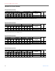
PowerFlex 700L Technical Data Maximum Motor Cable Lengths In the following tables, a “●” in any of the latter columns will indicate that this drive rating can be used with an AllenBradley Terminator (1204-TFA1/1204-TFB2) and/or Reflected Wave Reduction Device with Common Mode Choke (1204-RWC-17) or without choke (1204-RWR2). For the Terminator, the maximum cable length is 182.9 meters (600 feet) for 400/480/600V drives (not 690V). The PWM frequency must be 2 kHz.
PowerFlex 700L Technical Data PowerFlex 700L with 700VC Control, 600V Shielded/Unshielded Cable - Meters (Feet) 3B 870 2 (650) 4 3B 1275 2 (955) 1850V 365.8 (350) 61.0 (200) 91.4 (300) 61.0 (200) 83.8 (275) 1488V 182.9 (600) 76.2 (250) 152.4 (500) 53.3 (175) 137.2 (450) 1850V 365.8 (1200) 190.5 (625) 274.3 (900) 137.2 (450) 274.3 (900) Cat. No.
PowerFlex 700L Technical Data PowerFlex 700L with 700S Control, 480V Shielded/Unshielded Cable - Meters (Feet) No Solution HP Frame (kW) kHz 2 300 2 (224) 4 3A 600 2 (445) 4 3B (1) (2) 1150 2 (860) 4 1000V 12.2 (40) 12.2 (40) 12.2 (40) 12.2 (40) 12.2 (40) 12.2 (40) 1200V 30.5 (100) 30.5 (100) 30.5 (100) 30.5 (100) 30.5 (100) 30.5 (100) Reactor Only 1488V 61.0 (200) 61.0 (200) 61.0 (200) 61.0 (200) 61.0 (200) 61.0 (200) 1600V 121.9 (400) 121.9 (400) 121.9 (400) 121.9 (400) 121.9 (400) 121.
PowerFlex 700L Technical Data DPI Connections Frame 2 Drive Connection Points The PowerFlex 700L Frame 2 drive provides a number of cable connection points as shown in the drawing below. If an additional external HIM is required for the application, the HIM can be connected to the DPI port on the bottom of the drive. Only one additional external HIM device may be connected. The use of two external HIM devices is not supported.
PowerFlex 700L Technical Data Frame 3A Drive Connection Points The PowerFlex 700L provides a number of cable connection points as shown in the drawings below. If an additional external HIM is required for the application, the HIM can be connected to the DPI port on the bottom of the Power Module. Only one additional external HIM device may be connected. The use of two external HIM devices is not supported.
PowerFlex 700L Technical Data Frame 3B Drive Connection Points The PowerFlex 700L provides a number of cable connection points as shown in the drawings below. If an additional external HIM is required for the application, the HIM can be connected to the DPI port on the bottom of the Power Module. Only one additional external HIM device may be connected. The use of two external HIM devices is not supported.
PowerFlex 700L Technical Data Control Connections Frame 2 Frame 2 Control Terminal Locations ➊ 1 SHLD P1 ➋ 15 7 P2 SHLD 1 ➌ ➍ 1a15 1a14 1a13 1a12 1a11 1a10 1a9 1a8 1a7 1a6 1a5 1a4 1a3 1a2 1a1 PS- PS+ 1b14 1b13 1b12 1b11 1b10 1b9 1b8 1b7 1b6 1b5 1b4 1b3 1b2 1b1 PS- PS+ PE2 PE1 1b15 TB1 PE1PE2 Customer Connection Side Frame 2 Control Terminal Specifications Item ➊ Name PowerFlex 700 Vector Control or PowerFlex 700S Phase II Control Cassette Terminal Blocks ➋ Active
PowerFlex 700L Technical Data Frame 3 Frame 3A Control Terminal Locations ➊ POWER STS PORT MOD NET A NET B ➋➌ (Drive shown with doors removed) DC POSITIVE TB5 DC NEGATIVE 1 120 VAC 2 PRECHARGE COIL 3 120 VAC NEUTRAL 24 VDC 5 PR HARGE FEEDBACK ➍ GATE ENABLE 7 INDUCTOR OVERTEMP WIRE RANGE: 24-10 AWG (0.2-4 MM) STRIP LENGTH: 0.31 IN (8 MM) TORQUE: 8 IN-LB (0.
PowerFlex 700L Technical Data Frame 3B Control Terminal Locations ➋➌ ➊ POWER STS PORT MOD NET A NET B (Drive shown with doors removed) ➍ DC POSITIVE DC NEGATIVE TB5 1 120 VAC 2 PRECHARGE COIL 24 VDC 4 PR HARGE FEEDBACK ATE ENABLE 6 INDUCTOR OVERTEMP WIRE RANGE: 24-10 AWG (0.2-4 MM) STRIP LENGTH: 0.31 IN (8 MM) TORQUE: 8 IN-LB (0.
PowerFlex 700L Technical Data Control Highlights Active Converter Control File Monitor Group Parameters Current Rated Amps Input Current R Input Current S 001 Input Current T 002 Ground Current 003 Active Current 004 Reactive Current 005 I Imbalance 006 IT Overload 007 008 009 Voltage Rated Volts Input Voltage RS 010 Input Voltage ST 011 Input Voltage TR 012 DcLink Voltage 013 DcLink Ripple 014 V Imbalance 015 Power & Time Rated Power AC Line kW Motoring kWh 020 Regen kWh 021 Lifetime kWh 02
PowerFlex 700L Technical Data PowerFlex 700 Vector Control File Monitor Monit or Motor Control Motor Contr ol Speed Command Speed Comm and Dynamic Control Dynami c Contr ol Publication 20L-TD001A Group Metering Parameters Output Freq Commanded Speed Ramped Speed Speed Reference Commanded Torque Speed Feedback Drive Data Rated kW Motor Data Motor Type Motor NP Volts Motor NP FLA Torq Attributes Motor Cntl Sel Maximum Voltage Maximum Freq Compensation Flux Up Mode Flux Up Time SV Boost Filter Autotun
PowerFlex 700L Technical Data File Utility Group Direction Config HIM Ref Config MOP Config Drive Memory Utility Communication Comm unica tion Inputs & Outputs Inputs 34 & Outpu ts Parameters Direction Mode Save HIM Ref Save MOP Ref Param Access Lvl Reset To Defalts Load Frm Usr Set Diagnostics Drive Status 1 Drive Status 2 Drive Alarm 1 Drive Alarm 2 Speed Ref Source Start Inhibits Faults Fault Config 1 Fault Clear Fault Clear Mode Power Up Marker Fault 1 Code Alarms Alarm Config 1 Alarm Clear Ala
PowerFlex 700L Technical Data PowerFlex 700S Phase II Control Digital Current Regulator outperforms older style analog regulators in speed, repeatability and drift. Current Limit Current Limit Level PI Gain Block Derivative Gain Block Current Magnitude Calculator U Phase Motor Current V Phase Motor Current W Phase Motor Current Proportional Channel Integral Channel Negative Feed Forward reduces or eliminates overshoot during step speed changes. Helpful in preventing backup during stopping.
PowerFlex 700L Technical Data High Speed Analog & Digital I/O execute in 0.5 mSec or less to provide fast response and fast capture for registration information and position data. Output relays, optically isolated and differentially isolated I/O are supplied. Inertia Adaptation stabilizes inertia disconnect due to gear boxes or flexible couplings. It also provides broadband resonance compensation, allowing up to 4 times improvement to speed regulator bandwidth.
PowerFlex 700L Technical Data Standard Drive Specifications Category Agency Certification Specification Frame 2 Frame 3A/3B Listed to UL508C and CAN/CSA-C2.2 No. 14-05. UL Listing for Frame 2 is applicable up to 480V AC. UL Listing for Frame 3A and 3B is c UL US applicable up to 600V AC.
PowerFlex 700L Technical Data Specification Category Electrical Frame 2 Voltage Tolerance Vector Control: 700S Phase II Control: Control Input Frequency Tolerance: Input Phases: Displacement Power Factor: Efficiency: Maximum Short Circuit Current Rating: Actual Short Circuit Rating: Motor Lead Lengths: Method: Carrier Frequency: Output Voltage Range: Output Frequency Range Vector Control: 700S Phase II Control: Frequency Accuracy (Vector Control only) Digital Input: Analog Input: Frequency Control (Vect
PowerFlex 700L Technical Data Specification Category Control (continued) Frame 2 Stop Modes Vector Control: 700S Ph.
PowerFlex 700L Technical Data Derating Guidelines Altitude Above 1000 m (3280 ft.), derate the output current by 1% for every 100 additional meters (328 additional feet). This is applicable to filters and power modules. PowerFlex 700L 600/690V drives should not be used above 2000 m (6562 ft.) due to voltage spacing requirements. Ambient Frame 2 drives have a maximum ambient of 50°C (122°F). Frame 3A and 3B drives have a maximum ambient of 40°C (104°F).
PowerFlex 700L Technical Data Cooling Loop Options This section provides information about the various types of cooling loops. Liquid-to-Liquid Heat Exchanger The liquid-to-liquid heat exchanger utilizes a heat transfer plate to transfer heat from one liquid to another. This method requires a stable water supply from the user.
PowerFlex 700L Technical Data Liquid-to-Air Heat Exchanger The liquid-to-air heat exchanger utilizes radiator technology to transfer heat from a liquid to surrounding air. This is a simple closed loop system — it does not require a water supply from the user. However, this system requires surrounding air 5 to 10°C below the maximum operating temperature of the drive.
PowerFlex 700L Technical Data Chiller The chiller utilizes refrigerant to transfer heat from a liquid to air. This is a simple closed loop system — it does not require a water supply from the user. A chiller can achieve almost any coolant temperature required. Coolant temperature should be at or above ambient temperature to avoid condensation on drive components.
PowerFlex 700L Technical Data Recommended Cooling Loops Liquid-to-Liquid Heat Exchanger Selection Supply Loop Requirements (1) Minimum Flow @ Pressure (2) 15.1 LPM @ 0.83 bar (4 GPM @ 12 PSI) 22.7 LPM @ 0.83 bar (6 GPM @ 12 PSI) 56.8 LPM @ 0.83 bar (15 GPM @ 12 PSI) Drive Frame Size 2 3A 3B Maximum Pressure 8.62 bar (125 PSI) 8.62 bar (125 PSI) 8.62 bar (125 PSi) Temperature Range 0-40°C (32-104°F) 0-35°C (32-95°F) 0-35°C (32-95°F) Liquid-to-Liquid Heat Exchanger Cat. No.
PowerFlex 700L Technical Data Drive Coolant Requirements Recommended Coolants The table below lists approved sources and recommended coolants with appropriate corrosion inhibitors for the drive loop: Source Interstate Chemical http://www.interstatechemical.com/contact.htm Koolant Koolers/Dimplex Thermal Solutions http://www.koolantkoolers.com/index.php/nic=contact Dow Chemical http://www.dow.
PowerFlex 700L Technical Data Coolant Requirements for One Frame 2, 3A or 3B Drive Drive Frame Size 2 3A 3B Coolant Temperature Range 0-50°C (32-122°F) 0-40°C (32-104°F) 0-40°C (32-104°F) Minimum Coolant Flow Rate 30.3 LPM (8 GPM) 30.3 LPM (8 GPM) 56.8 LPM (15 GPM) (1) Pressure Drop (2) From Drive Inlet to Drive Coolant Type Outlet at Minimum Coolant Flow Rate 1.58 bar (23 PSI) WEG50 (3) or 0.35 bar (5 PSI) WPG50 (4) 0.
PowerFlex 700L Technical Data Drive Coolant Connections Frame 2 Drive Coolant connections for a Frame 2 drive are made using 37 degree flare fittings which have a: • 3/4-inch nominal size • “-12” SAE dash size • 1 1/16-12 UN/UNF-2B external thread size Wrench Flats 37° Flare Fitting Backup Wrench (use to prevent twisting during swivel nut tightening) Swivel Nut Frame 3A/3B Complete Drive Frame 3A/3B Complete Drive coolant connections are made using 37 degree flare fittings which have a: • 1-inch nominal
PowerFlex, Force Technology, DriveGuard, RSLogix, DriveExplorer, DriveTools SP, and DPI are trademarks of Rockwell Automation. Trademarks not belonging to Rockwell Automation are property of their respective companies. www.rockwellautomation.com Power, Control and Information Solutions Headquarters Americas: Rockwell Automation, 1201 South Second Street, Milwaukee, WI 53204-2496 USA,Tel: (1) 414.382.2000, Fax: (1) 414.382.