Model: DCSS09(2.5kW DCSS12(3.2kW DCSS18(5.0kW DCSS24(7.0kW DCSS28(7.8kW Cooling / Cooling / Cooling / Cooling / Cooling / 2.6kW Heating) 3.2kW Heating) 5.2kW Heating) 7.5kW Heating) 8.
CONTENTS SAFETY PRECAUTIONS ....................................................................................................1 NAMES OF PARTS .................................................................................................................4 INDOOR UNIT DISPLAY .........................................................................................................5 EMERGENCY FUNCTION & AUTO-RESTART FUNCTION ..............................................6 REMOTE CONTROLLER ................
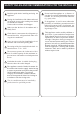
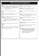
SAFETY RULES AND RECOMMENDATIONS FOR THE INSTALLER Do not install the appliance at a distance of less than 50 cm from inflammable substances (alcohol, etc.) Or from pressurised containers (e.g. spray cans). Read this guide before installing and using the appliance. During the installation of the indoor and outdoor units the access to the working area should be forbidden to children. Unforeseeable accidents could happen.
SAFETY RULES AND RECOMMENDATIONS FOR THE USER Never remain directly exposed to the flow of cold air for a long time. The direct and prolonged exposition to cold air could be dangerous for your health .Particular care should be taken in the rooms where there are children , old or sick people. Do not try to install the conditioner alone; always contact specialized technical personnel. Cleaning and maintenance must be carried out by specialised technical personnel.
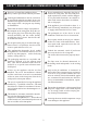
SAFETY RULES AND PROHIBITIONS Do not bend , tug or compress the power cord since this could damage it. Electrical shocks or fire are probably due to a damaged power cord. Specialised technical personnel only must replace a damaged power cord. Do not climb onto or place any heavy or hot objects on top of the appliance. Do not use extensions or power board. Do not direct the airflow onto plants or animals. Do not leave windows or doors open for long when the air conditioner is operating.
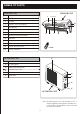
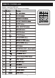
NAMES OF PARTS INDOOR UNIT No.
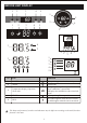
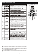
INDOOR UNIT DISPLAY 1 3 2 5 4 /O 1 5 2 2 1 3 4 4 5 3 4 3 2 1 3 4 5 1 2 3 4 5 3 1 No. 2 2 3 4 Led Function 1 POWER This symbol appears when the unit is power on 2 SLEEP SLEEP mode 3 Temperature display (if present) /Error code (1) Lights up during Timer operation when the air conditioner is operational (2)Displays the malfunction code when fault occurs. 4 TIMER Lights up during Timer operation.
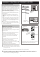
EMERGENCY FUNCTION & AUTO-RESTART FUNCTION AUTO-RESTART FUNCTION The appliance is preset auto - restart function by manufacturer. In case of a sudden power failure, the module memorizes the setting conditions before the power failure. when the power restores, the unit restarts automatically with all the previous settings preserved by the memory function. ON / OFF POWER SLEE P TIMER RUN Emergency button To deactivate the AUTO-RESTART function ,proceed as follows: 1.
REMOTE CONTROLLER Display Switch on/off the LED display (if present). The outlooking and some function of remote control may vary according to the model. The shape and position of buttons and indicators may vary according to the model, but their function is the same. The unit confirms the correct reception of each press button with a beep.
REMOTE CONTROLLER Remote controller DISPLAY Meaning of symbols on the liquid crystal display 8
REMOTE CONTROLLER Replacement of Batteries Remove the battery cover plate from the rear of the remote controller, by sliding it in the direction of the arrow. Install the batteries according the direction (+and -)shown on the Remote Controller. Reinstall the battery cover by sliding it into place. + Use 2 LRO 3 AAA (1.5V) batteries . Do not use rechargeable batteries . Replace the old batteries with new ones of the same type when the display is no longer legible.
OPERATING INSTRUCTIONS 10
OPERATING INSTRUCTIONS 11
OPERATING INSTRUCTIONS 12
OPERATING INSTRUCTIONS 13
OPERATING INSTRUCTIONS 14
PROTECTION The air conditioner is programmed for comfortable and suitable living conditions, if it is used in abnormal conditioner as below, certain safety protection features might come into effect. For T1 Climate condition models: No.
INSTALLATION MANUAL---Selecting the Installation Place Install the indoor unit on a strong wall that is not subject to vibrations. The inlet and outlet ports should not be obstructed:the air should be able to blow all over the room. Do not install the unit near a source of heat , steam,or flammable gas. Install the unit near an electric socket or private circuit. Do not install the unit where it will be exposed to direct sunlight.
INSTALLATION MANUAL---Installation of the Indoor unit Before starting installation, decide on the position of the indoor and outdoor units, taking into account the minimum space reserved around the units Do not install your air conditioner in a wet room such as a bathroom or laundry etc The installation site should be 250cm or more above the floor. To install, proceed as follows: 50 Installation of the mounting plate 1 Always mount the rear panel horizontally and vertically 2.
INSTALLATION MANUAL---Installation of the Indoor unit Refrigerant piping connection 1 The piping can be run in the 3 directions indicated by numbers in the picture . When the piping is run in direction 1or3, cut a notch along the groove on the side of the indoor unit with a cutter. Run the piping in the direction of the wall hole and bind the copper pipes , the drain pipe and the power cables together with the tape with the drain pipe at the bottom, so that water can flow freely.
INSTALLATION MANUAL---Installation of the Indoor unit INSTALLATION OF THE INDOOR UNIT After having connected the pipe according to the instructions, install the connection cables. Now install the drain pipe. After connection,lag the pipe, cables and drain pipe with the insulating material. 1. Arrange the pipes ,cables and drain hose well. 2. Lag the pipe joints with insulating material , securing it with vinyl tape. 3.
INSTALLATION MANUAL---Installation of the outdoor unit ELECTRICAL CONNECTIONS wiring diagram on the back of the cover 1. Remove the handle on the right side plate of outdoor unit. 2. Connect the power connection cord to the terminal board. Wiring should fit that of indoor unit. 3. Fix the power connection cord with wire clamp. 4. Confirm if the wire has been fixed properly. 5. An efficient earth connection must be ensured. 6. Recover the handle.
INSTALLATION MANUAL---Installation of the outdoor unit BLEEDING The air and humidity left inside the refrigerant circulation can cause compressor malfunction. After having connected the indoor and outdoor units, bleed the air and humidity from the refrigerant circulation using a vacuum pump. (1) Unscrew and remove the caps from the 2 - way and 3-way valves. (2) Unscrew and remove the cap from the service port. (3) Connect the vacuum pump hose to the service port.
INSTALLATION MANUAL---Information for the installer FIXED-SPEED TYPE MODEL capacity (Btu/h) Liquid pipe diameter Gas pipe diameter Lenght of pipe with standard charge Type of refrigerant(1) 12k 18k 24k 1/4 ( 6) 1/2 ( 12) 1/4 ( 6) 1/2 ( 12) 3/8 ( 9.52) 5/8 ( 15.88) capacity (Btu/h) Liquid pipe diameter Gas pipe diameter Lenght of pipe with standard charge Type of refrigerant(1) 5m 5m 5m R410A R410A 5m R410A INVERTER TYPE MODEL 9k 1/4 ( 6) 3/8 ( 9.
INSTALLATION MANUAL---Information for the installer WIRING DIAGRAM For different models, the wiring diagram may be different. Please refer to the wiring diagrams pasted on the indoor unit and outdoor unit respectively. On indoor unit, the wiring diagram is pasted under the front panel; On outdoor unit, the wiring diagram is pasted on the backside of the outdoor handle cover.
INSTALLATION MANUAL---Information for the installer CABLE WIRES SPECIFICATION 12k 9k FIXED-SPEED TYPE MODEL capacity (Btu/h) 24k 18k sectional area 2 2.5mm2 AWG14 H05RN-F 2 N 1.5mm AWG16 1.5mm AWG16 2 2 L 1.5mm AWG16 1.5mm AWG16 1.5mm AWG16 E 1.5mm2 AWG16 1.5mm2 AWG16 1.5mm AWG16 2.5mm2 AWG14 H05RN-F N 1.5mm2 1.5mm2 1.5mm2 0.75mm2 L / / / 0.75mm 1 1.5mm2 1.5mm2 1.5mm2 0.75mm2 2 0.75mm 0.75mm 0.75mm 0.75mm 3 0.75mm2 0.75mm2 0.75mm2 0.75mm2 1.
MAINTENANCE Periodic maintenance is essential for keeping your air conditioner efficient. Before carrying out any maintenance , disconnect the power supply by taking the plug out from the socket. INDOOR UNIT ANTIDUST FILTERS 1. Open the front panel following the direction of the arrow 2. Keeping the front panel raised with one hand, take out the air filter with the other hand 3. Clean the filter with water ; if the filter is soiled with oil,it can be washed with warm water (not exceeding 45 ).
TROUBLESHOOTING MALFUNCTION POSSIBLE CAUSES Power failure/plug pulled out Damaged indoor/outdoor unit fan motor Faulty compressor thermomagnetic circuit breaker The appliance does not Faulty protective device or fuses. operate Loose connections or plug pulled out It sometimes stops operating to protect the appliance.
CONTACT DETAILS Glen Dimplex Australia Pty Ltd 1340 Ferntree Gully Road Scoresby VIC 3179 Australia Ph: 1300 556 816 Web: www.dimplex.com.au Glen Dimplex New Zealand Ltd 38 Harris Road East Tamaki, Auckland New Zealand Ph: 09 274 8265 Web: www.dimplex.co.