Service Manual Chelsea Freestanding Corner Fireplace Model Number DCF7850 EMSC UL Part Number 6901820200 IMPORTANT SAFETY INFORMATION: Always read this manual first before attempting to service this fireplace. For your safety, always comply with all warnings and safety instructions contained in this manual to prevent personal injury or property damage. Dimplex North America Limited 1367 Industrial Road Cambridge ON Canada N1R 7G8 1-888-346-7539 www.dimplex.
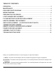
TABLE OF CONTENTS OPERATION. . . . . . . . . . . . . . . . . . . . . . . . . . . . . . . . . . . . . . . . . . . . . . . . . . . . . . . . . 3 Maintenance . . . . . . . . . . . . . . . . . . . . . . . . . . . . . . . . . . . . . . . . . . . . . . . . . . . . . . 4 Exploded Parts Diagram. . . . . . . . . . . . . . . . . . . . . . . . . . . . . . . . . . . . . . . .
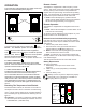
OPERATION Remote Control The controls are located inside the door panel on the lower side of the Corner Standing Stove (Figure 1). Figure 1 Door Panel The fireplace is supplied with a radio frequency remote control. This remote control has a range of approximately 50 feet (15.25 m), it does not have to be pointed at the fireplace and can pass through most obstacles (including walls). It is supplied with one of hundreds of independent frequencies to prevent interference with other units.
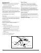
Maintenance Glass Cleaning WARNING: Disconnect power before attempting any maintenance or cleaning to reduce the risk of fire, electric shock or damage to persons. Light Bulb Replacement Allow at least five (5) minutes for light bulbs and heater to cool off before touching bulbs to avoid accidental burning of skin. Light bulbs need to be replaced when you notice a dark section of the flame or when the clarity and detail of the log exterior disappears.
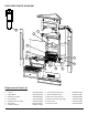
Exploded Parts Diagram 13 5 1 3 10 6 4 8 9 12 7 11 2 Replacement Parts List Replacement Part: 1. Log Set . . . . . . . . . . . . . . . . . . . . . . . . . 0439040100RP 2. Flicker Motor. . . . . . . . . . . . . . . . . . . . . 2000140300RP 3. Reflector Assembly. . . . . . . . . . . . . . . . 5900080600RP 4. Light Harness . . . . . . . . . . . . . . . . . . . . 2500170200RP 5. Partially Reflective Glass. . . . . . . . . . . .5900470100RP 6. Thermostat . . . . . . . . . . . . . . . . . . . . .
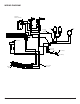
Wiring Diagram RECEIVER, REMOTE CONTROL Switch 2 1 Switch 3 2 1 01 Lampholder wire assembly Flicker Motor Lamp Blower Motor THERMOSTAT Wire of wide blade of plug Cord Wide blade (N) Narrow Blade (L) Element Bank Wire from Cutout 24 GA - Red 6 www.dimplex.
PREPARATION FOR SERVICE Tools Required: Philips head screwdrivers -Large and Medium Head Needle nose pliers. WARNING: If the fireplace was operating prior to servicing, allow at least 10 minutes for light bulbs and heating elements to cool off to avoid accidental burning of skin. WARNING: Disconnect power before attempting any maintenance to reduce the risk of electric shock or damage to persons. 1.
receiver on the back left side panel. b. Proceed to the wire ties along the upper housing panel above the receiver, (below the flicker rod) and work your way from left to right. c. The last tab to be released will be right below the light bulb on the right. 8. Pull this upper panel farther down as much as you can it to allow access to the light sockets and wire harness from the back. 9. Remove the (2) wire nuts on the interior side of the panel that connect the light harness wires to their power source.
heater housing area and pull through the wire tie to free up the motor. ! NOTE: The white wire connects to the wire nut connecting the other white or neutral wires. The black wire connects to the wire nut connecting the red from the switch and the smooth black from the light harness. 13. Attach the white and the black wires of the new flicker motor back into the respective wire nuts. 14. Attach the flicker motor to the flicker motor mounting bracket. 15.
the wires so you can re-position the panels in a way to allow more room for parts access. ! NOTE: These wire ties will be re-inserted when service is complete therefore should not be cut off unless you have the same type of replacement ties. 6. Release wire tie mounting tabs in the following order: a. Start with the wire ties below the remote control receiver on the back left side panel. b.
stat. 12. Re-position the new thermostat back into the original opening and re-attach the thermostat to the front panel using the two original small screws. 13. Align the thermostat dial in the correct position and push it back onto the shaft of the thermostat control. 14. Push all of the mountable wire ties back into the correct holes on the housing panels making sure they are secure. You will have to move the panel up closer into the upper cavity.
9. One lead of the power cord is a “Piggy-Back” connection at the 3-Position switch, which connects 2 wires on to one prong on the switch. 10. Separate the orange wire from the “Piggy-back” connector on the white wire from the power cord. 11. Disconnect the wire nut connected to the other half of the power cord with the group of white “neutral” wires. 12. With a pair of needle nose pliers, squeeze the strain relief bushing that holds the power cord in place onto the back panel remove the cord. 13.
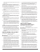
ASSEMBLY PART PICTURES Thermostat Control Dial Heater On/Off Switch 3-Position Switch Flicker Rod & Left Bracket Remote Control Receiver Flicker Motor and Mounting Bracket Upper Heater Housing Panel Bottom Heater Housing Panel Power Cord Heater Assembly Light Harness Sockets Interior View of Flicker Rod Light Bulbs - 2 Small Base Candelabra Bulbs Back side of Upper Heater Housing Panel Socket Rings Sockets in Socket Mounting Bracket Light/Wire Harness 13
Example of Mountable Wire Tie Heater Assembly Connections Red Wire Connects Motor to Heater Elements (comes already attached) Blower/Fan “Piggy Back” from Upper Element to Heater Motor Fan Motor Connector to Thermostat (White) “Piggy Back” to Heater Switch Top and Bottom Element Connection Elements Electrical Connections in Heater Housing 1st • • • • • Wire Nut Whites from: Thermostat Power Cord Flicker Motor Remote Control Receiver “N” JP3 Black (Ribbed) from Light Harness 2nd Wire Nut: • Red from
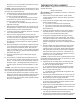
Heater Assembly Connections Heater On/Off Switch 3-Position Switch Black Wire from Heater Assembly Tan Wire Connects to JP2 on Remote Control Receiver Connects to Heater On/Off Switch and to the Lampholder Wire Assembly Jumper from Middle Prong of On/Off Switch ! NOTE: Not a Piggy Back Connector but has 2 wires ! NOTE: Not a Piggy Back Connector but has 2 wires into one blade connector at the ON/ OFF Switch Connects to the “L” on the Remote Control Receiver White on Power Cord Thermostat Control R
Troubleshooting Guide Problem Cause Solution General Circuit breaker trips or fuse blows when unit is turned on Short in unit wiring. Trace wiring in unit. Improper circuit current rating Additional appliances may exceed the current rating of the circuit breaker or fuse. Plug unit into another outlet or install unit on a dedicated 15 amp circuit. Unit turns on or off by itself Remote control has a similar frequency to other remotes in the area.
Problem Cause Solution Heater Heater is not turning off Heater is not turning on, but flame effect is still functioning Improper operation Refer to Operation Section Defective Heater On/Off Switch Replace Heater On/Off Switch Defective Thermostat Replace Thermostat Defective Remote Control Receiver Replace Remote Control Receiver Improper operation Refer to Operation Section Loose Wiring Trace wiring in unit Defective Heater On/Off switch Replace Heater On/Off switch Defective Thermostat