
Service manual

10 www.dimplex.com
the wires so you can re-position the panels in a way to
allow more room for parts access.
!
NOTE: These wire ties will be re-inserted when service
is complete therefore should not be cut off unless you have
the same type of replacement ties.
Release wire tie mounting tabs in the following order: 6.
a. Start with the wire ties below the remote control
receiver on the back left side panel.
b. Proceed to the wire ties along the upper housing
panel above the receiver, (below the icker rod) and
work your way from left to right.
c. The last tab to be released will be right below the
light bulb on the right.
Pull this upper panel farther down as much as you can 7.
and reposition it to allow access to the switch housing
above this panel on the top right hand side.
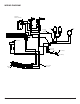
Locate the switch being replaced, (either the 3-Position 8.
or the Heat ON/OFF switch).
Take note of the original location of each wire con-9.
nected to the switch that needs replacing and pull them
off. Some may have a “Piggy-Back” connection, con-
necting 2 wires on to one prong on the switch. It may
be helpful to try and keep these two wires together for
re-assembly.
Note the orientation of the switches. Depress the tabs 10.
on the short ends of the switch that secure the switch
to the housing from behind the panel, and push the
switch out through the front. Using needle nosed pliers
will give you a better grip and t to depress both these
tabs at the same time.
Push the new switch in place following the original 11.
orientation.
Push all of the mountable wire ties back into the cor-12.
rect holes on the housing panels making sure they are
secure. You will have to move the panel up closer into
the upper cavity. This will greatly reduce the amount
of lead or give in the wires and the workspace, on the
unit.
!
NOTE: If the wire ties are not securing properly, use a
at instrument to slightly spread the tabs farther apart and
then re-insert into the appropriate holes in the panel.
Re-assemble the rebox and cabinet in reverse order, 13.
taking care that the wires are guided through the cutout
openings on the left and right of the housing panels
and no wires are touching the heater assembly blower/
fan once re-assembled.
THERMOSTAT REPLACEMENT
Tools required: Phillips head screw driver (both small and
medium size head)
Needle nosed pliers.
CAUTION: Follow “Preparation for Service” instructions
before proceeding.
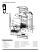
Remove the 6 screws that hold the “upper” heater-1.
housing panel located on the panel, above the remote
control receiver.
These screws are along the edge of this upper panel 2.
where it meets the side:
a. (2) screws on the bottom near the back left,
b. (2) screws on the bottom near the back right,
c. (2) screws on the bottom near the center front of
this middle panel.
Carefully pull this panel down as long as the length of 3.
the wires will allow. There won’t be much space be-
cause of the wire ties attached to the panel.
Through the slight gap between the upper housing 4.
panel and the upper cavity of the rebox, use needle
nose pliers to release all of the wire-ties from the lower
panels by squeezing the wire-tie tab ends from the
outside of the panels. See order of releasing wire tabs
below.
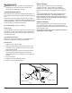
With the needle nose pliers, squeeze the wire tie tabs 5.
enough to reduce the spread of the tabs and push it
through the hole on the panel. While squeezing these
tabs, gently pull on the wire and tie from the opposite
side of the panel until it comes free. This will free up
the wires so you can re-position the panels in a way to
allow more room for parts access.
!
NOTE: These wire ties will be re-inserted when service
is complete therefore should not be cut off unless you have
the same type of replacement ties.
Release wire tie mounting tabs in the following order: 6.
a. Start with the wire ties below the remote control
receiver on the back left side panel.
b. Proceed to the wire ties along the upper housing
panel above the receiver, (below the icker rod) and
work your way from left to right.
c. The last tab to be released will be right below the
light bulb on the right.
Pull this upper panel farther down as much as you can 7.
and reposition it to allow access to the switch housing
above this panel on the top right hand side.
Locate the thermostat control dial on the left hand side 8.
on the front of the replace and pull it forward, off the
shaft of the thermostat control.
Remove the 2 screws that fasten the thermostat control 9.
to the front panel. These screws require a small head
on a Philips screwdriver.
Carefully guide the thermostat down and out through 10.
the opening underneath the thermostat housing.
Disconnect the 2 wires from the thermostat, noting their 11.
original location and reconnect onto the new thermo-