
Service manual


15
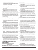
Remote Control Receiver
“N” (JP3) - Connects to Wire Nut with White wires
in Heater Housing
Switch Output (JP2) - Connects to On side of
3-Position Switch
Orange “L” JP1 from 3-Position Switch – Piggy
Backed to Power Cord.
3-Position Switch
Thermostat Control
Black Wire from Heater Assembly
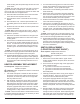
Jumper from Middle Prong of
On/Off Switch
!
NOTE: Not a Piggy Back
Connector but has 2 wires into
one blade connector at the ON/
OFF Switch
Connects to the “L” on the Re-
mote Control Receiver
White on Power Cord
Tan Wire Connects to JP2 on
Remote Control Receiver
Heater On/Off
Switch
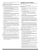
Heater Assembly Connections
Connects to Heater On/Off
Switch and to the Lampholder
Wire Assembly
!
NOTE: Not a Piggy Back
Connector but has 2 wires
Stand Off Mounting Tabs