
Service manual

7
PREPARATION FOR SERVICE
Tools Required: Philips head screwdrivers
-Large and Medium Head
Needle nose pliers.
WARNING: If the replace was operating prior to ser-
vicing, allow at least 10 minutes for light bulbs and heating
elements to cool off to avoid accidental burning of skin.
WARNING: Disconnect power before attempting any
maintenance to reduce the risk of electric shock or damage
to persons.
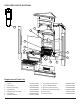
Stabilizing straps may have been installed attaching 1.
this corner tting cabinet to the wall on the left and right
back/corner panels. If so, remove them rst by remov-
ing the screw anchoring them to the wall.
Pull the cabinet away from the wall. 2.
Unplug the replace from the outlet. 3.
On the (2) backside, corner-tting panels of the exterior 4.
cabinet, release the 4 “CAM LOCKS”, (2) on the left
and (2) on the right near the top. This is done by using
a large Philips head screwdriver and turning the each
cam lock ¼ turn counter-clockwise until the “—” and “+”
symbols line up horizontally.
With cam locks released, carefully lift the top panel off 5.
the cabinet. The top panel will have long metal shafts
attached to it, which are part of the interior cam lock
mechanism. Be careful not to break these off.
Lay the cabinet down on the oor or your work surface, 6.
onto the back/corner panel with the switches closest to
the oor.
!
NOTE: If the surface you are using as a work area on
is a nished surface that is prone to scratches (i.e. hard-
wood ooring), it is recommended that a protective barrier
be used underneath, (i.e. cloth, cardboard, thick plastic).
Remove the decorative metallic grill on the front of the 7.
cabinet, which covers the heat area of the replace.
This is magnetically attached and can be remove by
pulling it away starting in one of the corners or grasping
it at the grill openings.
Remove the (2) brackets found inside the body of the 8.
cabinet that attach the rebox-insert to the interior of
the cabinet. There are (2) Philips screws in each of the
(2) brackets.
Slide the rebox out from the top opening of the cabi-9.
net.
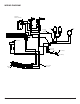
Remove the (1) Philips screw located on the lower 10.
housing back panel below the power cord.
Remove 6 screws in total from the “bottom” heater-11.
housing panel, (2) on the bottom left edge, (2) on the
bottom right edge, and (2) on the front face of the hous-
ing panel, just above the heat vent. Once screws are
removed from the left panel, you will have to turn the
rebox ¼ turn so that it rests on the right back panel
with the switches being farthest away from the oor.
Once these screws are removed, pull off the bottom 12.
heater-housing panel and rest it just in front of the
replace.
!
NOTE: Wires inside the heater housing are attached to
the panels with mountable wire ties so the panel cannot be
moved very far.
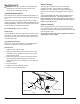
Release the mountable wire-ties from the heater-hous-13.
ing panel by using needle nose pliers to squeeze the
wire-tie tab ends from the exterior side of the panels.
Squeeze the tabs enough to reduce the spread of the
tabs and push it through the hole on the panel. While
squeezing these tabs, gently pull on the wire tie from
inside the panel, (opposite side) until it comes through.
This will free up the wires and allow more room to ac-
cess parts.
!
NOTE: These wire ties will be re-inserted when service
is complete therefore they should not be cut off unless you
have the same type of replacement ties.
Proceed to the next instructions in the manual relating 14.
to the repair being performed.
LIGHT HARNESS REPLACEMENT
Tools required: Phillips head screw driver.
Needle nosed pliers.
CAUTION: Follow “Preparation for Service” instructions
before proceeding.
Remove the 6 screws that hold the “upper” heater-1.
housing panel located on the panel, above the remote
control receiver.
These screws are along the edge of this upper panel 2.
where it meets the side:
a. (2) screws on the bottom near the back left,
b. (2) screws on the bottom near the back right,
c. (2) screws on the bottom near the center front of
this middle panel.
Carefully pull this panel down as long as the length of 3.
the wires will allow. The wires are secured by wire ties
to this panel and do not allow much space for access.
Through the slight gap between the upper housing 4.
panel and the upper cavity of the rebox, use needle
nose pliers to release all of the wire-ties from the lower
panels by squeezing the wire-tie tab ends from the
outside of the panels. See order of releasing wire tabs
below.
With the needle nose pliers, squeeze the wire tie tabs 5.
enough to reduce the spread of the tabs and push it
through the hole on the panel. While squeezing these
tabs, gently pull on the wire and tie from the opposite
side of the panel until it comes free. This will free up
the wires so you can re-position the panels in a way to
allow more room for parts access.
!
6. NOTE: These wire ties will be re-inserted when
service is complete therefore should not be cut off un-
less you have the same type of replacement ties.
Release wire tie mounting tabs in the following order: 7.
a. Start with the wire ties below the remote control