
Service manual

8 www.dimplex.com
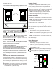
receiver on the back left side panel.
b. Proceed to the wire ties along the upper housing
panel above the receiver, (below the icker rod) and
work your way from left to right.
c. The last tab to be released will be right below the
light bulb on the right.
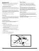
Pull this upper panel farther down as much as you can 8.
it to allow access to the light sockets and wire harness
from the back.
Remove the (2) wire nuts on the interior side of the 9.
panel that connect the light harness wires to their
power source.
!
NOTE: Both light harness wires are black. Take note
of which wires are secured with which wire nut. The ribbed
black wire is the “Neutral” and goes with the group of neu-
tral white wires, which are connected with one wire nut).
The smooth black wire from the light harness is the “Load”
“L1” wire, and is grouped with another black and a red wire
in the other wire nut.
Remove the light bulbs located on the socket mounting 10.
bracket, behind the upper-housing panel by unscrewing
them counter-clockwise.
Remove the sockets by turning the socket rings counter 11.
clockwise; then pushing each socket out of the mount-
ing bracket.
Light harness wires are fed through an opening below 12.
the bracket to the wire nuts on the interior of the hous-
ing. Pull the light harness wires out from this opening
and feed the wires from the new light harness through
this opening. Reconnect each wire to the appropriate
wire nuts as mentioned in the “NOTE” above in step 9.
Unscrew rings from the new sockets. Position the 13.
new sockets into the correct openings on the mounting
bracket and secure the sockets into place by turning
the rings clockwise onto the thread on each socket.
Push all of the mountable wire ties back into the cor-14.
rect holes on the housing panels making sure they are
secure. You will have to move the panel up closer into
the upper cavity. This will greatly reduce the amount
of lead or give in the wires and the workspace, on the
unit.
!
NOTE: If the wire ties are not securing properly, use a
at instrument to slightly spread the tabs farther apart and
then re-insert into the appropriate holes in the panel.
Re-assemble the rebox in reverse order, taking care 15.
that the wires are guided through the cutout openings
on the left and right of the housing panels and no wires
are touching the heater assembly blower/fan once re-
assembled.
FLICKER MOTOR/FLICKER ROD
REPLACEMENT
Tools required: Phillips head screw driver.
Needle nosed pliers.
CAUTION: Follow “Preparation for Service” instructions
before proceeding.
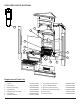
Remove the 6 screws that hold the “upper” heater-1.
housing panel located on the panel, above the remote
control receiver.
These screws are along the edge of this upper panel 2.
where it meets the side:
a. (2) screws on the bottom near the back left,
b. (2) screws on the bottom near the back right,
c. (2) screws on the bottom near the center front of
this middle panel.
Carefully pull this panel down as long as the length of 3.
the wires will allow. There won’t be much space be-
cause of the wire ties attached to the panel.
Through the slight gap between the upper housing 4.
panel and the upper cavity of the rebox, use needle
nose pliers to release all of the wire-ties from the lower
panels by squeezing the wire-tie tab ends from the
outside of the panels. See order of releasing wire tabs
below.
With the needle nose pliers, squeeze the wire tie tabs 5.
enough to reduce the spread of the tabs and push it
through the hole on the panel. While squeezing these
tabs, gently pull on the wire and tie from the opposite
side of the panel until it comes free. This will free up
the wires so you can re-position the panels in a way to
allow more room for parts access.
!
NOTE: These wire ties will be re-inserted when service
is complete therefore should not be cut off unless you have
the same type of replacement ties.
Release wire tie mounting tabs in the following order: 6.
a. Start with the wire ties below the remote control
receiver on the back left side panel.
b. Proceed to the wire ties along the upper housing
panel above the remote control receiver, (below the
icker rod) and work your way from left to right.
c. The last tab to be released will be right below the
light bulb on the right.
Pull this upper panel farther down as much as you can 7.
to allow access to the icker motor and bracket above
this panel.
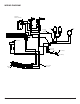
Remove the 2 screws on the right side of the upper 8.
housing panel that holds the icker motor bracket on
above it.
Carefully slide the left side of the icker motor rod out 9.
of the plastic bushing in the left bracket (closest to the
thermostat).
Remove the icker rod off the icker motor by grasping 10.
the rod and rubber gasket attached to the motor shaft,
then twist and pull away from the motor until comes off
the motor shaft. Set the rod aside.
Remove the 2 screws that attach the icker motor to 11.
the icker motor mounting bracket noting the orienta-
tion of the motor.
Disconnect (unscrew) the wire nuts that attach the 12.
icker motor wires to their power source located inside