
Service manual

9
heater housing area and pull through the wire tie to free
up the motor.
!
NOTE: The white wire connects to the wire nut connect-
ing the other white or neutral wires. The black wire con-
nects to the wire nut connecting the red from the switch and
the smooth black from the light harness.
Attach the white and the black wires of the new icker 13.
motor back into the respective wire nuts.
Attach the icker motor to the icker motor mounting 14.
bracket.
Attach the icker rod, - twist and push the icker rod 15.
and rubber gasket onto the shaft of the new icker mo-
tor.
Slide the left side of the icker rod into the plastic bush-16.
ing in the left bracket.
!
NOTE: Make sure that the rod has not bent. This can
cause the reectors to rub against the housing, making a
noise when in operation.
Reconnect the icker motor bracket on the right to the 17.
middle housing panel with the 2 screws to the bottom
housing panel.
Push all of the mountable wire ties back into the cor-18.
rect holes on the housing panels making sure they are
secure. You will have to move the panel up closer into
the upper cavity. This will greatly reduce the amount
of lead or give in the wires and the workspace, on the
unit.
!
NOTE: If the wire ties are not securing properly, use a
at instrument to slightly spread the tabs farther apart and
then re-insert into the appropriate holes in the panel.
Re-assemble the rebox in reverse order, taking care 19.
that the wires are guided through the cutout openings
on the left and right of the housing panels and no wires
are touching the heater assembly blower/fan once re-
assembled.
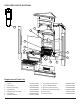
HEATER ASSEMBLY REPLACEMENT
Tools Required: Philips head screwdriver
Needle nose pliers
CAUTION: Follow “Preparation for Service” instructions
before proceeding.
Use needle nose pliers to release the wire ties below 1.
the remote control receiver, which hold the wires onto
the panels, as well as any other ties on the right side
that may obstruct access.
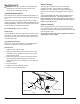
With the pliers, squeeze the wire tie tabs on the back-2.
side of the panel enough to reduce the spread of the
tabs and push it through the hole on the panel. While
squeezing these tabs, pull on the wire tie from inside
the panel, (opposite side) until it comes free. This will
free up the wires so you can re-position the heater-
housing panel in a way to allow more room for access.
!
NOTE: These wire ties will be re-inserted when service
is complete therefore should not be cut off unless you have
the same type of replacement ties.
Turn the heater-housing panel over and remove the 4 3.
screws, which attach the housing panel to the heater
assembly bracket. Lay the panel down again.
Remove the 4 screws attaching the bracket onto the 4.
heater assembly.
Remove the wires connected to the heater assembly 5.
at the motor and elements on the right hand side. Be
sure to note their original locations and reconnect onto
the new heater assembly in the same position.
Re-attach the bracket to the heater assembly and then 6.
to the lower heater housing panel.
Push all of the mountable wire ties back into the cor-7.
rect holes on the housing panels making sure they are
secure. You will have to move the panel up closer into
the upper cavity. This will greatly reduce the amount
of lead or give in the wires and the workspace, on the
unit.
!
NOTE: If the wire ties are not securing properly, use a
at instrument to slightly spread the tabs farther apart and
then re-insert into the appropriate holes in the panel.
Re-assemble the rebox and cabinet in reverse order, 8.
taking care that the wires are guided through the cutout
openings on the left and right of the housing panels
and no wires are touching the heater assembly blower/
fan once re-assembled.
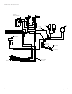
SWITCH REPLACEMENT –
(3-POSITION OR HEAT ON/OFF)
Tools required: Phillips head screw driver.
Needle nosed pliers.
CAUTION: Follow “Preparation for Service” instructions
before proceeding.
Remove the 6 screws that hold the “upper” heater-1.
housing panel located on the panel, above the remote
control receiver.
These screws are along the edge of this upper panel 2.
where it meets the side:
a. (2) screws on the bottom near the back left,
b. (2) screws on the bottom near the back right,
c. (2) screws on the bottom near the center front of
this middle panel.
Carefully pull this panel down as long as the length of 3.
the wires will allow. There won’t be much space be-
cause of the wire ties attached to the panel.
Through the slight gap between the upper housing 4.
panel and the upper cavity of the rebox, use needle
nose pliers to release all of the wire-ties from the lower
panels by squeezing the wire-tie tab ends from the
outside of the panels. See order of releasing wire tabs
below.
With the needle nose pliers, squeeze the wire tie tabs 5.
enough to reduce the spread of the tabs and push it
through the hole on the panel. While squeezing these
tabs, gently pull on the wire and tie from the opposite
side of the panel until it comes free. This will free up