PARTS & SERVICE MANUAL EWM-COPPER EWM-SS DFP20-BW1009 7400300000R01
Table of Contents OPERATION ......................................................................................................... 3 MAINTENANCE .................................................................................................... 5 EXPLODED VIEW ................................................................................................ 7 REPLACEMENT PARTS ...................................................................................... 8 WIRING DIAGRAM ..........................
OPERATION A 15 Amp, 120-volt circuit is required. A dedicated circuit is preferred but not essential in all cases. A dedicated circuit will be required if, after installation, the circuit breaker trips or fuse blows on a regular basis when the heater is operating. Additional appliances on the same circuit may exceed the current rating of the circuit breaker.
RESETTING THE TEMPERATURE CUTOFF SWITCH This unit is equipped with a thermostat that controls the temperature of the room. It does this by turning the heater on and off. The heater is protected with a safety device to prevent overheating. Should the heater overheat, an automatic cut out will turn the heater off and it will not come back on without being reset. To reset the temperature cut-off switch turn the main power switch to the OFF position and wait five minutes before switching the unit back on.
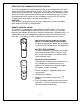
MAINTENANCE WARNING: Disconnect power before attempting any maintenance or cleaning to reduce the risk of fire, electric shock or damage to persons. LIGHT BULB REPLACEMENT Allow at least 5 minutes for light bulbs to cool before touching bulbs to avoid accidental burning of skin. Light bulbs need to be replaced when you notice a dark section of the flame or when the clarity and detail of the log exterior disappears. There are two bulbs under the log set which generate the flames and embers.
GLASS CLEANING The front glass is cleaned in the factory during the assembly operation. During shipment, installation, handling, etc., the front glass may collect dust particles, these can be removed by dusting lightly with a clean dry cloth. To remove fingerprints or other marks, the glass can be cleaned with a damp cloth. The glass should be completely dried with a lint free cloth to prevent water spots. To prevent scratching, do not use abrasive cleaners or spray liquids on the glass surface.
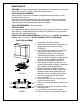
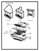
EXPLODED VIEW EWM-COPPER EWM-SS DFP20-BW1009 08 07 05 11 12 04 02 01 7
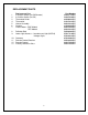
REPLACEMENT PARTS 1 2 3 4 5 6 7 8 9 10 11 12 13 Replacement Part 3-Position Switch (On/Off/Remote) 2-Position Switch (On/Off) Thermostat Knob Thermostat Heater Assembly Cordset Flicker Motor – EMC Models DFP Models Reflector Rod Lower Light Harness – Incandescent Light (MOD 0) Halogen Light Grommet Remote Control Receiver Remote Control Partially Reflective Glass 8 Part Number 2800071100RP 2800070200RP 8800000300RP 2300150100RP 2000230100RP 4100040200RP 2000140300RP 2000220100RP 5900080600RP 2500170100RP
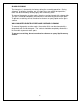
WIRING DIAGRAM R E C E IV E R , R E MO TE C O N T R O L S w it ch 2 1 S w it c h 3 2 1 01 F lick e r Mo tor L amp L am ph olde r w ire a s sem bly B low e r M oto r T H E R MO S TA T W ir e o f w ide bla de of p lug W id e b lade (N ) C or d N ar ro w B lad e ( L) W ire fro m C uto ut 24 G A - R ed E lem ent B an k MOD 0 9
If the unit was operating prior to servicing allow at least 10 minutes for light bulbs and heating element to cool off to avoid accidental burning of skin. Disconnect power before attempting any maintenance or cleaning to reduce the risk of electric shock or damage to persons. TO REPLACE MAIN ON/OFF SWITCH 1. Unplug the unit from the outlet. 2. Remove the two mounting screws from the bottom front of the heater assembly. 3.
If the unit was operating prior to servicing allow at least 10 minutes for light bulbs and heating element to cool off to avoid accidental burning of skin. Disconnect power before attempting any maintenance or cleaning to reduce the risk of electric shock or damage to persons. TO REPLACE FLAME MOTOR/FLAME ROD 1. Unplug the unit from the outlet. 2. Remove the two mounting screws from the bottom front of the heater assembly. 3.
If the unit was operating prior to servicing allow at least 10 minutes for light bulbs and heating element to cool off to avoid accidental burning of skin. Disconnect power before attempting any maintenance or cleaning to reduce the risk of electric shock or damage to persons. TO REPLACE HEATER ON/OFF SWITCH 1. Unplug the unit from the outlet. 2. Remove the two mounting screws from the bottom front of the heater assembly. 3.
If the unit was operating prior to servicing allow at least 10 minutes for light bulbs and heating element to cool off to avoid accidental burning of skin. Disconnect power before attempting any maintenance or cleaning to reduce the risk of electric shock or damage to persons. TO REPLACE HEATER ASSEMBLY 1. Unplug the unit from the outlet. 2. Remove the two mounting screws from the bottom front of the heater assembly. 3.
If the unit was operating prior to servicing allow at least 10 minutes for light bulbs and heating element to cool off to avoid accidental burning of skin. Disconnect power before attempting any maintenance or cleaning to reduce the risk of electric shock or damage to persons. TO REPLACE HEATER THERMOSTAT CONTROL 1. Unplug the unit from the outlet. 2. Remove the two mounting screws from the bottom front of the heater assembly. 3.
If the unit was operating prior to servicing allow at least 10 minutes for light bulbs and heating element to cool off to avoid accidental burning of skin. Disconnect power before attempting any maintenance or cleaning to reduce the risk of electric shock or damage to persons. TO REPLACE REMOTE CONTROL RECEIVER 1. Unplug the unit from the outlet. 2. Remove the two mounting screws from the bottom front of the heater assembly. 3.
If the unit was operating prior to servicing allow at least 10 minutes for light bulbs and heating element to cool off to avoid accidental burning of skin. Disconnect power before attempting any maintenance or cleaning to reduce the risk of electric shock or damage to persons. TO REPLACE THE POWER CORD 1. Unplug the unit from the outlet. 2. Remove the two mounting screws from the bottom front of the heater assembly. 3.
TROUBLE SHOOTING GUIDE APPEARANCE Problem Flame frozen. Probable Cause Loose wiring or defective flame motor. Solution Check all wiring for loose connections, repair/replace as necessary. If wiring connections are suitable, replace flame motor. Service Manual Reference Page 9 Problem Flame not bright, flame not visible. Probable Cause Loose wiring or burnt light bulb(s). Solution Check all wiring for loose connections, repair/replace as necessary. Check upper and lower light bulb(s).
TROUBLE SHOOTING GUIDE HEATER ASSEMBLY Problem Heating element is glowing red. Probable Cause Normal operation or defective heating assembly. Solution Small glowing sections of the element are considered normal. If larger glowing sections are causing the heater to trip the thermal cut out, unplug, discontinue use and replace the heater assembly. Service Manual Reference Page 11 Problem Heater is not turning on. Probable Cause Defective switch or loose wiring or defective heater assembly.
TROUBLE SHOOTING GUIDE HEATER ASSEMBLY Problem Heater is not turning off. Probable Cause Defective switch or loose wiring or defective heater assembly. Solution Check all wiring for loose wiring connections, repair/replace as necessary. If all wiring connections are suitable check heater on/off switch & heater assembly for proper operation. Replace as necessary. Service Manual Reference Heater on/off switch Page 10 Heater assembly Page 11 Problem Heater fan runs continuously.
TROUBLE SHOOTING GUIDE NOISE Problem Excessive noise with the heater on. Probable Cause Excessively dirty blower or defective heater assembly. Solution Remove the heater assembly cover and clean the dust out of the blower, if noise persists replace heater assembly or see below. Service Manual Reference Page 11 Problem Grinding or excessive noise with the heater off. Probable Cause Defective flame motor. Solution Replace flame motor with a new one.
TROUBLE SHOOTING GUIDE GENERAL Problem Circuit breaker trips or fuse blows when the unit is turned on. Probable Cause Improper circuit current rating. Solution Additional appliances may exceed the current rating of the circuit breaker or fuse. Plug the unit into another outlet or install on a dedicated circuit with a 15 amp rating. If the unit continues to trip circuit breakers or blow fuses check all wiring for loose connections, repair/replace as necessary.
1367 Industrial Road Cambridge ON Canada N1R 7G8 1-888-346-7539 www.dimplex.com In keeping with our policy of continuous product improvement, we reserve the right to make changes without notice.