
Service manual


OPERATION
A 15 Amp, 120-volt circuit is required. A dedicated circuit is preferred but not
essential in all cases. A dedicated circuit will be required if, after installation, the
circuit breaker trips or fuse blows on a regular basis when the heater is
operating. Additional appliances on the same circuit may exceed the current
rating of the circuit breaker.
WARNING: Ensure the power cord is not installed so that it is pinched or against
a sharp edge and ensure that the power cord is stored or secured to avoid
tripping or snagging to reduce the risk of fire, electric shock or injury to persons.
Construction and electrical outlet wiring must comply with local building codes
and other applicable regulations to reduce the risk of fire, electric shock and
injury to persons.
Do not attempt to wire your own new outlets or circuits. To reduce the risk of fire,
electric shock or injury to persons, always use a licensed electrician.
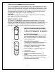
The controls are located on the lower right side of the wall mounted electric
fireplace. (FIGURE 1)
A. MAIN ON/OFF SWITCH
The switch has two ON positions marked with and “Manual”. The
“Manual“ position is for manual operation. In this position the built-in remote
control is by-passed. The position is for operating the unit with the provided
remote control. When in position the unit is operated with the ON and OFF
buttons of the remote control. When the switch is in the center position the unit is
off.
B. HEATER ON/OFF SWITCH
The HEATER ON/OFF SWITCH supplies power to the heater fan and the heater
element.
C. HEATER THERMOSTAT CONTROL
To adjust the temperature to your individual requirements, turn the thermostat
control clockwise all the way to turn on the heater. When the room reached the
desired temperature, turn the thermostat knob counter clockwise until you hear a
click. Leave in this position to maintain the room temperature at this setting. For
additional heat, turn clockwise until you hear the click again and the heater will turn
on. To turn the heater off, switch the HEATER ON/OFF SWITCH to the OFF
position.
3
MOD 0 MOD A
FIGURE 1 (LOWER RIGHT SIDE)