Service Manual Model Number: DWF-13XX UL Part Number 6908760100 IMPORTANT SAFETY INFORMATION: Always read this manual first before attempting to service this fireplace. For your safety, always comply with all warnings and safety instructions contained in this manual to prevent personal injury or property damage. Dimplex North America Limited 1367 Industrial Road Cambridge ON Canada N1R 7G8 1-888-346-7539 www.dimplex.
TABLE OF CONTENTS OPERATION. . . . . . . . . . . . . . . . . . . . . . . . . . . . . . . . . . . . . . . . . . . . . . . . . . . . . . . . . 3 MAINTENANCE . . . . . . . . . . . . . . . . . . . . . . . . . . . . . . . . . . . . . . . . . . . . . . . . . . . . . . 4 EXPLODED PARTS DIAGRAM . . . . . . . . . . . . . . . . . . . . . . . . . . . . . . . . . . . . . . . . . . 5 REPLACEMENT PARTS. . . . . . . . . . . . . . . . . . . . . . . . . . . . . . . . . . . . . . . . . . . . . . . .
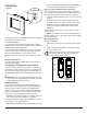
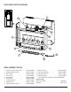
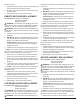
OPERATION Figure 1 A B The manual controls for the electric fireplace are located on the right side of the unit (Figure 1). A. 3-Position Switch The switch has two On positions marked with “I” and “II”. The “I” position is for manual operation. In this position the built-in remote control is bypassed. The “II” position is for operating the unit with the provided remote control. When in “II” position the unit is operated with the On and Off buttons of the remote control.
MAINTENANCE WARNING: Disconnect power before attempting any maintenance or cleaning to reduce the risk of fire, electric shock or damage to persons. Partially Reflective Glass Cleaning The Partially Reflective Glass is cleaned in the factory during the assembly operation. During shipment, installation, handling, etc., the Partially Reflective Glass may collect dust particles; these can be removed by dusting lightly with a clean dry cloth.
EXPLODED PARTS DIAGRAM 9 1 10 7 8 12 2 11 3 4 6 5 REPLACEMENT PARTS 1. 2. 3. 4. 5. 6. 7. 8. 9. Heater Assembly (with Cutout). . . . . . . Partially Reflective Glass . . . . . . . . . . . Flame Panel. . . . . . . . . . . . . . . . . . . . . Power Cord . . . . . . . . . . . . . . . . . . . . . Flicker Motor . . . . . . . . . . . . . . . . . . . . Flicker Rod . . . . . . . . . . . . . . . . . . . . . 3-Position Switch . . . . . . . . . . . . . . . . . On/Off Switch . . . . . . . . . . . . . . . . .
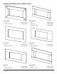
FRAMES AND MEDIA REPLACEMENT PARTS DWF-1322MA 1. Trim . . . . . . . . . . . . . . . . . . . . . . . . . . . 690879012ARP 2. River Rock Media. . . . . . . . . . . . . . . . . 1400080100RP DWF-1325WN 1. Trim . . . . . . . . . . . . . . . . . . . . . . . . . . . 6908820138RP 2. Walnut Tray . . . . . . . . . . . . . . . . . . . . . 1124800138RP 3. River Rock Media. . . . . . . . . . . . . . . . . 1400080100RP DWF-1327B 1. Trim . . . . . . . . . . . . . . . . . . . . . . . . . . . 690885010FRP 2.
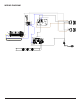
WIRING DIAGRAM TF "L" OUT P REMOTE CONTROL RECEIVER BOARD T N F "L" IN P P P F T F TOP TYP. BOTTOM TYP.
3-POSITION SWITCH REPLACEMENT Tools Required: Philips head screwdriver Flat head screwdriver WARNING: If the fireplace was operating prior to servicing, allow at least 10 minutes for light bulbs and heating elements to cool off to avoid accidental burning of skin. WARNING: Disconnect power before attempting any maintenance to reduce the risk of electric shock or damage to persons. 1. Carefully remove the loose media from the front tray, if applicable. 2.
release the wires. 7. Depress the retainer clips on the rear of the switch and push the switch out through the opening. 8. Properly orient and insert the new switch and connect all of the wiring. 9. Reassemble in the reverse order as above.
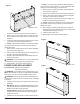
Figure 5 Mounting Screws and the five screws along the front edge. (Figure 3) 5. Gently remove the top panel, laying it on the work surface so that all of the components can easily be seen. (Figure 4) 6. Locate the heater assembly and disconnect the wiring connections noting their original locations. ! NOTE: A flat head screwdriver can be used to gently pry between the end of the connector and the switch to release the wires. 7. Remove the 4 screws that secure the heater assembly to the back panel.
Figure 8 LED Lights PARTIALLY REFLECTIVE GLASS REPLACEMENT Tools Required: Phillips Head Screwdriver WARNING: If the fireplace was operating prior to servicing, allow at least 10 minutes for light bulbs and heating elements to cool off to avoid accidental burning of skin. WARNING: Disconnect power before attempting any maintenance to reduce the risk of electric shock or damage to persons. 1. Carefully remove the loose media from the front tray, if applicable. 2.
the unit and your work surface, (i.e. cloth, cardboard, thick plastic) to avoid scratching your work surface. 4. Remove the ten screws around the outside flange of the end panel. (Figure 6) 5. Remove the eight screws on the end panel. (Figure 7) 6. Gently open the end panel, being careful not to strain the wires connected to the switches 7. Remove the partially reflective glass by sliding it out of the unit. 8.
TROUBLESHOOTING GUIDE PROBLEM CAUSE SOLUTION General Circuit breaker trips or fuse blows when unit is turned on Short in unit wiring. Trace wiring in unit. Improper circuit current rating Additional appliances may exceed the current rating of the circuit breaker or fuse. Plug unit into another outlet or install unit on a dedicated 15 amp circuit. Unit turns on or off by itself Remote control has a similar frequency to other remotes in the area.
PROBLEM CAUSE SOLUTION Heater Heater is not turning off Heater is not turning on, but flame effect is still functioning Heater is turning off after a couple of minutes of operation Heater emits an odor Improper operation Refer to Operation Section Defective Heater On/Off Switch Replace Heater On/Off Switch Defective Remote Control Receiver The remote control and the remote control receiver needs to be replaced. Reinitialize the remote control to the remote control receiver after installation.