Owner’s Manual Model DWF3651 IMPORTANT SAFETY INFORMATION: Always read this manual first before attempting to install or use this fireplace. For your safety, always comply with all warnings and safety instructions contained in this manual to prevent personal injury or property damage. To view the full line of Dimplex products, please visit www.dimplex.
Table of Contents Welcome & Congratulations . . . . . . . . . . . . . . . . . 3 IMPORTANT INSTRUCTIONS . . . . . . . . . . . . . . . . 4 Quick Reference Guide. . . . . . . . . . . . . . . . . . . . . 6 Fireplace Installation . . . . . . . . . . . . . . . . . . . . . . 7 Operation. . . . . . . . . . . . . . . . . . . . . . . . . . . . . . . 11 Maintenance. . . . . . . . . . . . . . . . . . . . . . . . . . . . 14 Warranty. . . . . . . . . . . . . . . . . . . . . . . . . . . . . . . 15 Replacement Parts. . .
Welcome & Congratulations Thank you and congratulations for purchasing an electric fireplace from Dimplex. Please use our convenient online registration page to record your model and serial numbers for future reference at www.dimplex.com/register Rating Label with Model Number and Serial Number Please carefully read and save these instructions. CAUTION: Read all instructions and warnings carefully before starting installation.
IMPORTANT INSTRUCTIONS When using electrical appliances, basic precautions should always be followed to reduce the risk of fire, electric shock, and injury to persons, including the following: the electric fireplace has been dropped or damaged in any manner, contact Dimplex Technical Service at 1-888-346-7539. ① Read all instructions before using the electric fireplace. ⑨Do not use outdoors. ② This fireplace is hot when in use. To avoid burns, do not let bare skin touch hot surfaces.
IMPORTANT INSTRUCTIONS exhaust in any manner. Do not use on soft surfaces, like a bed, where openings may become blocked. cian should new circuits or outlets be required. ⑰ All electrical heaters have hot and arcing or sparking parts inside. Do not use in areas where gasoline, paint, or flammable liquids are used or stored or where the unit will be exposed to flammable vapors. ㉔ Disconnect all power supply before performing any cleaning, maintenance or relocation of the unit.
Quick Reference Guide 1092 mm 43.0” 500 mm 19.7” 459 mm 18.1” 915 mm 36.0” 144 mm 5.7” 796 mm 31.4” 152 mm 6.0” 1092 mm 43.0” 230 mm 9.1” ! 6 549 mm 21.6” Figure 1 53 mm 2.1” 3. The heater may emit a slight, harmless odor when first used. This odor is a normal condition caused by the initial heating of internal heater parts. 4. For dimensions of your fireplace, refer to Figure 1. 25 mm 1.0” 1. Before using the fireplace verify the circuit breakers for the unit on? 2.
Fireplace Installation Site Selection The unit is packaged with two types of mounting options: • Wall mounting, Surface • Support feet, table top ! NOTE: A 15 Amp, 120 Volt circuit is required. A dedicated circuit is preferred but not essential in all cases. A dedicated circuit will be required if, after installation, the circuit breaker trips or the fuse blows on a regular basis when the heater is operating. Additional appliances on the same circuit may exceed the current rating of the circuit breaker.
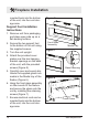
Fireplace Installation to mount the unit on a wall, above an electrical outlet. Access to the electrical outlet must be maintained. Ensure the installation meets the national and state/provincial electrical codes. ! NOTE: It is recommended that the bottom of the unit not be mounted higher than 1020mm (40") from the Fireplace Installation ground to maintain an optimized viewing angle of the flame. CAUTION: Ensure that the top of the unit is at least 610mm (24") from the ceiling or any object (i.e.
Fireplace Installation 5. 6. 7. 8. 9. bracket. Adjust the wall-mounting bracket so the bubble on the level is centered between the two black lines. Mark 3 other mounting screw locations, on the wall, ensuring that the wall bracket stays level. Install the supplied wall anchors on the drywall marked locations by placing a #2 Phillips screwdriver into the recess of the anchor. Press the anchor into the wall in the desired marked position while turning the anchor clockwise until it is flush with the wall.
Fireplace Installation inserted back into the bottom of the unit, into the cord storage area. Figure 6 Support Feet Installation Instructions 1. Remove unit from packaging and place open side up on a flat working surface. 2. Secure the two support feet to the bottom of the unit using the supplied screws. 3. Turn the unit upright. 4. Attach the provided cover plates over the two hanging bracket openings on the back of the unit, with the provided screws (Figure 8). 5.
Operation Figure 9 Figure 10 A C D E F A B C D E F G H Floating DisplayTM The unit can be controlled by either the manual controls which are located on the right side of the fireplace or the remote (Figure 9 & 10). The fireplace is supplied with an IR multifunction remote control. ! NOTE: To operate correctly, the remote control must be pointed towards the Floating DisplayTM.
Operation High Heat and Off. → Activated by pressing the button on the unit or the remote. • Indicated by the (low heat) or the (high heat) icon and the intake temperature being displayed on the On Screen Display, for 5 seconds before turning off. ! NOTE: After the heater is switched off, there is a 60 second fan delay, where the fan will continue running before turning off. ! NOTE: The unit can be operated in Heat Only Mode.
Operation or the is pressed the On Screen Display will indicate "--". F. Color Themes Different presets of ambient lighting color combinations contained in the unit. → Changed by repeatedly pressing the corresponding button on the remote or the unit. • Cycles through the different preset ambient lighting settings of the unit, this includes different combinations of colours of the top lighting, flame base and media lighting (if applicable).
Operation unit and waiting 5 minutes before plugging the unit back in. CAUTION: If you need to continuously reset the heater, unplug the unit and call technical support at 1-888-346-7539. Remote Control Battery Replacement To replace the battery: 1. Slide battery cover open on the remote control. Correctly install one 3 Volt (CR2032 [longer life] or CR2025) battery in the battery holder. 2. Close the battery cover. Battery must be recycled or disposed of properly.
Warranty Products to which this limited warranty applies This limited warranty applies to the following models of your newly purchased Dimplex electric fireplace DWF3651. This limited warranty applies only to purchases made in any province of Canada except for Yukon Territory, Nunavut, or Northwest Territories or in any of the 50 States of the USA (and the District of Columbia) except for Hawaii and Alaska. This limited warranty applies to the original purchaser of the product only and is not transferable.
Warranty replacement is not commercially practicable or cannot be timely made, Dimplex may, in lieu of repair or replacement, choose to refund the purchase price for such product or part. • Limited warranty service will be performed solely by dealers or service agents of Dimplex authorized to provide limited warranty services.
Replacement Parts Heater Assembly (with Cutout) . . . . . . . . . . . . . . . . . . . . . . . . . 2203610400RP Front Glass . . . . . . . . . . . . . . . . . . . . . . . . . . . . . . . . . . . . . . . . 5902440100RP Partially Reflective Glass. . . . . . . . . . . . . . . . . . . . . . . . . . . . . . 5902420100RP Power Cord. . . . . . . . . . . . . . . . . . . . . . . . . . . . . . . . . . . . . . . . 4100010900RP Flicker Motor. . . . . . . . . . . . . . . . . . . . . . . . . . . . . . . . . . . . . . .