Service Manual Model DWF3651 DWF5252B Part Number 6908492100 6909770159 IMPORTANT SAFETY INFORMATION: Always read this manual first before attempting to service this fireplace. For your safety, always comply with all warnings and safety instructions contained in this manual to prevent personal injury or property damage. Dimplex North America Limited 1367 Industrial Road Cambridge ON Canada N3H 4W3 1-888-346-7539 www.dimplex.
TABLE OF CONTENTS Operation. . . . . . . . . . . . . . . . . . . . . . . . . . . . . . . . . . . . . . . . . . . . . . . . . . . . . . . . . . . 3 Maintenance. . . . . . . . . . . . . . . . . . . . . . . . . . . . . . . . . . . . . . . . . . . . . . . . . . . . . . . . . 4 Exploded Parts Diagram. . . . . . . . . . . . . . . . . . . . . . . . . . . . . . . . . . .
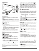
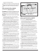
OPERATION Figure 1 A C D E F Floating DisplayTM The unit can be controlled by either the manual controls which are located on the right side of the fireplace or the remote (Figure 1 & 2). The fireplace is supplied with an IR multifunction remote control. ! NOTE: To operate correctly, the remote control must be pointed towards the Floating DisplayTM. ! NOTE: Before attempting any operation with the remote, pull the plastic insulator strip out from between the remote casing and battery cover. A.
• Indicated by the second digit on the Floating Display™ changing to show: “H” (high), and “L” (low). H. Sleep Timer The Sleep Timer can be set to automatically shut off the fireplace after a preset time (from 30 minutes to 8 hours). → To set the timer press the timer button on the remote, repeatedly, until the desired time is displayed. • The On Screen Display will display the different times as it is adjusted.
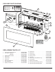
EXPLODED PARTS DIAGRAM 8 7 1 12 11 14 15 9 17 3 10 4 6 18 19 5 13 2 REPLACEMENT PARTS LIST 1. Heater Assembly (with Cutout). . . . . . . . . . . . 2203610400RP 10. Switchboard. . . . . . . . . . . . . . . . . . . . . . . . . . 3001520100RP 2. Front Glass - DWF3651 . . . . . . . . . . . . . . . . 5902440100RP DWF5252. . . . . . . . . . . . . . . . . 5902410400RP 11. Relay Board . . . . . . . . . . . . . . . . . . . . . . . . . . 3001440200RP 3. Partially Reflective Glass. . . . . . . .
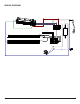
WIRING DIAGRAM CN3 CN4 CN6 CN6 CN4 CN3 6 www.dimplex.
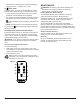
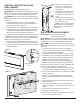
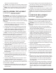
PARTIALLY REFLECTIVE GLASS REPLACEMENT Figure 5 Tools Required: Phillips head screwdriver WARNING: If the fireplace was operating prior to servicing, allow at least 10 minutes for light bulbs and heating elements to cool off to avoid accidental burning of skin. WARNING: Disconnect power before attempting any maintenance to reduce the risk of electric shock or damage to persons. 1.
Figure 6 Heater Assembly Relay Board AC/DC Adapter Display/Control Board Switch Board 10.Carefully transfer the wire connections from the original control board onto the new control board. 11. Re-assemble the fireplace in reverse order from the instructions above. ! NOTE: If any tie wraps were removed, replace and ensure that none of the wires are pinched during reassembly. ! NOTE: Be sure that the flanges on the end panel are positioned on the interior of the outside panel of the fireplace.
order from the instructions above. ! NOTE: If any tie wraps were removed, replace and ensure that none of the wires are pinched during reassembly. ! NOTE: Be sure that the flanges on the end panel are positioned on the interior of the outside panel of the fireplace.
order from the instructions above. ! NOTE: If any tie wraps were removed, replace and ensure that none of the wires are pinched during reassembly. ! NOTE: Be sure that the flanges on the end panel are positioned on the interior of the outside panel of the fireplace.
FLICKER MOTOR REPLACEMENT Figure 8 Tools Required: Phillips head screwdriver Flat head screwdriver Needle-nose pliers WARNING: If the fireplace was operating prior to servicing, allow at least 10 minutes for light bulbs and heating elements to cool off to avoid accidental burning of skin. Media Tray Retaining Screws End Panel Screws Figure 9 Flicker Motor Flicker Rod End Bracket LED Light Strip Bracket Flicker Rod Middle Bracket Flicker Rod 12.
for it to go all the way down into the bracket. 15. Reconnect the flicker motor wires, according to their original configuration. 16. Re-assemble the remainder of the fireplace in reverse order from the instructions above. ! NOTE: If any tie wraps were removed, replace and ensure that none of the wires are pinched during reassembly. ! NOTE: Be sure that the flanges on the end panel are positioned on the interior of the outside panel of the fireplace.
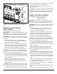
TROUBLESHOOTING GUIDE PROBLEM CAUSE SOLUTION PART NUMBER General Circuit breaker trips or fuse blows when unit is turned on Short in unit wiring. Trace wiring in unit. Improper circuit current rating Additional appliances may exceed the current rating of the circuit breaker or fuse. Plug unit into another outlet or install unit on a dedicated 15 amp circuit.
PROBLEM CAUSE SOLUTION Heater Only one level of heat is coming on Heater wiring has become loose Check the heater wiring Defective relay board Replace the relay board Heater is not turning Off Improper operation Refer to Operation Section Defective switch board Replace the switch board 3001520100RP Defective thermistor Replace the thermistor 3001560100RP Defective relay board Replace the relay board 3001440200RP Defective display / control board Replace the display / control board 3001