
Installation Sheet

7204380100R09
Down-Flo Wall Heater
EWA-C, 1, 1.5, 2 kW Series
WARNING: To reduce the risk of re, do not store or use
gasoline or other ammable vapors or liquids in the vicinity of
the heater.
CAUTION: High temperature, risk of re, keep electrical
cords, drapery, furnishings, and other combustibles at least
3 feet (0.9 m) from the front of the heater.
Recessed Installation
1. Allow 12” (30cm) of service cable for connecting to wall
box. Remove 6” (15cm) of the outer jacket and strip the
individual conductors ¼” (6mm) from the end.
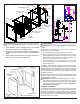
2. Cut a wall opening 14 9/16” (37cm) high by 11 ¼” (28.5cm)
wide (see Figure 1). Allow a minimum of 2” (5cm) clearance
around wall opening to accomodate heater frame. Depth
of wall opening must be 3 ¼” (8.3cm) minimum, measured
from nished wall surface.
3. Remove the screws securing heater assembly to the wall
box and separate. Keep all screws for heater reassembly.
4. Remove rear knockout at top corner of wall box and insert
½ cable connector. Bring service leads through connector
and secure end of cable to the connector.
Installation Instructions
IMPORTANT INSTRUCTIONS
When using electrical appliances, basic precautions should al-
ways be followed to reduce the risk of re, electric shock, and
injury to persons, including the following:
1. Read all instructions before using the heater.
2. The heater is hot when in use. To avoid burns, do not let
bare skin touch hot surfaces. The trim around the heater
outlet becomes hot during heater operation. Keep com-
bustible materials, such as furniture, pillows, bedding, pa-
pers, clothes, and curtains at least 3 ft (0.9 m) from the
front of the unit and keep them away from the sides and
rear.
3. Extreme caution is necessary when any heater is used by
or near children or invalids and whenever the unit is left
operating and unattended.
4. Do not operate any heater after it malfunctions. Discon-
nect power at the service panel and have the heater ins-
pected by a reputable electrician before reusing.
5. Do not use outdoors.
6. To disconnect the unit, turn the controls off, and then
switch off at main power supply panel.
7. Do not insert or allow foreign objects to enter any venti-
lation or exhaust opening as this may cause an electric
shock or re, or damage to the heater.
8. To prevent a possible re, do not block air intake or ex-
haust in any manner.
9. All electrical heaters have hot and arcing or sparking parts
inside. Do not use in areas where gasoline, paint, or am-
mable liquids are used or stored.
10. Do not modify this heater. Use it only as described in this
manual. Any other use not recommended by the manufac-
turer may cause re, electric shock or injury to persons.
SAVE THESE INSTRUCTIONS
5. For safety, each wall heater is provided with a grounding
screw located in the upper right corner of the wall box.
Connect ground lead and tighten screw for good electrical
connection.
6. Place wall box in wall opening so the welded side brackets
rest on nished wall surface, and secure box with four #10
Philips head wood screws, 1 ½” long (not provided). Insert
the wood screws through the inner set of ange holes at
both top and bottom. Alternate holes are provided in sides
of box for mounting to wood framing. (If wall box is installed
prior to application of nished wall surface, set box to allow
for wall thickness).
!
NOTE: When mounting wall box to hard wall surface, predrill
mounting and clearance holes to prevent splitting wall surface.
7. Check nameplate on heater to make sure you are connect-
ing to the proper voltage. Remove any packing material
or debris from the heater assembly and wall box. Then
connect service leads.
8. Place heater assembly into the wall box. Check fan to see
that it turns freely, and service leads are clear of fan area.
Secure heater assembly to the wall box with four sheet
metal screws (provided).
9. Carefully position grille over heater assembly so that pro-
truding switch and thermostat shaft do not bind against
grille. Secure grille to heater assembly using two Phillips
head sheet metal screws (provided). Push press-t ther-
mostat knob on shaft.
10. Install the frame to the grille, securing its upper back edge
behind the lip on the top of the wall box, and its lower edge
with the single screw.
11. Energize heater circuit and test heater (see operating
instructions).
Surface Installation
1. Allow 25” (63cm) of service cable for connecting the heater
(see Fig. 2). Remove all but 2” (5cm) of outer jacket and
strip individual conductors ¼” (6mm) from end.
2. Mount surface box to the wall using the four provided #8
- ¾” (19 mm) Philips head wood screws, inserted through
mounting holes on the back side anges. (For hard wall
surfaces, pre-drill mounting holes to prevent splitting wall
surface.)
3. Install ½ cable connector in hole on bottom of surface
boxnear right side. Feed service leads through and secure
end of cable to the connector.
4. Remove the rear knockout on top of heater wall box near
right side and insert bushing (provided). Feed service wires
through bushing. Secure wall box to surface box with four
sheet metal screws (provided with the surface box). Screws
are inserted through the inside holes on the anges.
5. Proceed with steps 7 through 11 inclusive in recessed
heater installation instructions.
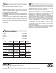
Wiring
Two conductor non-metallic sheath cable with ground wire is
recommended for recessed installation of these heaters while
two conductor, metallic sheath cable (BX) is recommended for
surface installations. Use number 12 gauge wire for all models.
Each heater should be on an individual, properly fused circuit.