Service Manual Model Number: DFR2551L DFR2551G UL Part Number 6908922259 6908922559 IMPORTANT SAFETY INFORMATION: Always read this manual first before attempting to service this fireplace. For your safety, always comply with all warnings and safety instructions contained in this manual to prevent personal injury or property damage. Dimplex North America Limited 1367 Industrial Road Cambridge ON Canada N3H 4W3 1-888-346-7539 www.dimplex.
TABLE OF CONTENTS Operation. . . . . . . . . . . . . . . . . . . . . . . . . . . . . . . . . . . . . . . . . . . . . . . . . . . . . . . . . . . 3 Maintenance. . . . . . . . . . . . . . . . . . . . . . . . . . . . . . . . . . . . . . . . . . . . . . . . . . . . . . . . . 4 Exploded Parts Diagram. . . . . . . . . . . . . . . . . . . . . . . . . . . . . . . . . . .
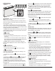
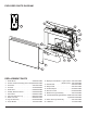
OPERATION Figure 1 A C D E F heat) or the (high heat) icon and the intake temperature will continuously be displayed on the On Screen Display. ! NOTE: The heater may emit a slight, harmless odor when first used. This odor is a normal condition caused by initial heating of internal heater. D & E. Floating DisplayTM WARNING: This electric firebox must be properly installed before it is used.
H. MAINTENANCE Sleep Timer The Sleep Timer can be set to automatically shut off the fireplace after a preset time (from 30 minutes to 8 hours). → To set the timer press the timer button on either the remote or the unit, repeatedly, until the desired time is displayed. • The On Screen Display will display the different times as it is adjusted. Once the timer has begun, pressing the button will display the time remaining before the unit turns Off.
EXPLODED PARTS DIAGRAM 2 16 14 15 4 13 19 12 3 5 18 1 6 7 REPLACEMENT PARTS 1. 2. 3. 4. 5. 6. 7. 8. 9. 10. 11. Flicker Motor. . . . . . . . . . . . . . . . . . . . . 2000500100RP Ceramic Heater Assembly (with Cutout).2203690100RP Thermistor. . . . . . . . . . . . . . . . . . . . . . . 3001560100RP Cord Set . . . . . . . . . . . . . . . . . . . . . . . . 4100090204RP Flicker Rod . . . . . . . . . . . . . . . . . . . . . . 5902620300RP Partially Reflective Panel. . . . . . . . . . . .
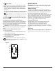
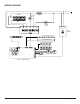
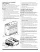
WIRING DIAGRAM L N ELEMENT M BLOWER MOTOR CUTOUT +T° M FLICKER MOTOR 120V / 12V ~ AC/DC ADAPTER AC / DC RELAY BOARD MEDIA BED RGB LED STRIP SWITCHBOARD LOGSET ASSEMBLY MEDIA BED LED ASSEMBLY LOGSET LED ASSEMBLY THERMISTOR LED LIGHT ASSEMBLY DISPLAY-CONTROL BOARD 6 www.dimplex.
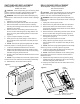
SWITCHBOARD REPLACEMENT Tools Required: Phillips Head Screwdriver Needle Nose Pliers CAUTION: If unit was operating prior to servicing allow at least 10 minutes for lights, heating elements and top panel to cool off to avoid accidental burning of skin. WARNING: Disconnect power before attempting any maintenance to reduce the risk of electric shock or damage to persons. 1. Unplug the unit from power outlet. 2. Remove the front glass and set aside in a safe place. 3.
! NOTE: If any tie wraps were removed, replace and ensure that none of the wires are pinched during reassembly. 11. Reassemble in the reverse order as above. AC/DC ADAPTER REPLACEMENT Tools Required: Phillips Head Screwdriver Flat Head Screwdriver CAUTION: If unit was operating prior to servicing allow at least 10 minutes for lights, heating elements and top panel to cool off to avoid accidental burning of skin.
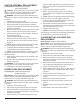
HEATER ASSEMBLY REPLACEMENT Tools Required: Phillips Head Screwdriver Flat Head Screwdriver CAUTION: If unit was operating prior to servicing allow at least 10 minutes for lights, heating elements and top panel to cool off to avoid accidental burning of skin. WARNING: Disconnect power before attempting any maintenance to reduce the risk of electric shock or damage to persons. 1. Unplug the unit from power outlet. 2. Remove the front glass and set aside in a safe place. 3.
FLAME LED LIGHT ASSEMBLY REPLACEMENT Tools Required: Phillips Head Screwdriver CAUTION: If unit was operating prior to servicing allow at least 10 minutes for lights, heating elements and top panel to cool off to avoid accidental burning of skin. WARNING: Disconnect power before attempting any maintenance to reduce the risk of electric shock or damage to persons. 1. Unplug the unit from power outlet. 2. Remove the front glass and set aside in a safe place. 3.
brackets to the mantel. 4. Remove the front glass and set aside in a safe place. 5. Pull the front edge of the plastic Ember Bed or plastic grate up and forward until the rear tab releases from the ledge located at the bottom of the Partially Reflective Panel. (Figure 7) ! IMPORTANT: Only handle the Log Set by the Ember Bed. ! NOTE: Log Set fits tightly into firebox, some force may be necessary to remove. 6. Reassemble in the reverse order as above.
TROUBLESHOOTING GUIDE PROBLEM CAUSE SOLUTION PART NUMBER General Circuit breaker trips or fuse blows when unit is turned on Short in unit wiring. Trace wiring in unit. Improper circuit current rating Additional appliances may exceed the current rating of the circuit breaker or fuse. Plug unit into another outlet or install unit on a dedicated 15 amp circuit.
PROBLEM CAUSE SOLUTION Heater Heater is not turning off Improper operation Refer to Operation Section Defective switchboard Replace switchboard 3001520100RP Defective thermistor Replace thermistor 3001560100RP Defective relay board Replace the relay board Defective display/control board Replace the display/control board Improper operation Refer to Operation Section The ambient temperature around the unit is too low (≤ 32°F/0°C) Allow the heater to run for 10-15 minutes to allow the motor